NI USB-6000 User Guide | © National Instruments | 9
Pinout and Signal Descriptions
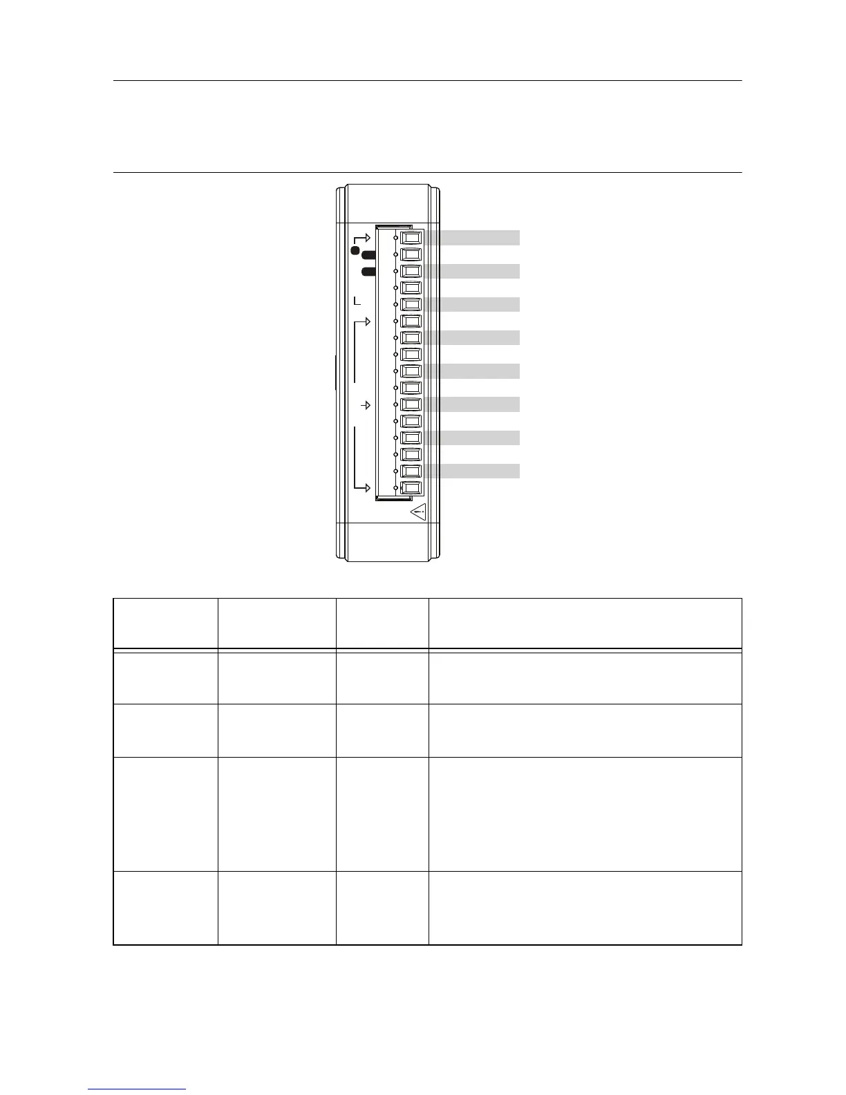
Figure 4 shows the pinout of the NI USB-6000. Refer to Table 4 for a detailed description of
each signal.
Figure 4. NI USB-6000 Pinout
Table 4. Signal Descriptions
Signal
Name
Reference Direction Description
D GND — — Digital Ground—The reference point for
digital signals.
AI GND — — Analog Input Ground—The reference
point for analog input measurements.
P0.<0..3> D GND Input or
Output
Port 0 Digital I/O
Channels0to3—Configure each signal
individually as an input or output.
Refer to the Digital I/O section for more
information.
PFI 0 D GND Input PFI 0—An edge counter input. Refer to the
Using PFI 0 as a Counter Source section for
more information.
D GND
P0.0/PFI 0
P0.1/PFI 1
P0.2
P0.3
AI GND
AI 0
AI 1
AI 2
AI 3
AI GND
AI 4
AI 5
AI 6
AI 7
AI GND
0
7 4 06 5 312 23
AI (±10V)
1
P0.x / PFI xx