14 | ni.com | NI USB-6000 User Guide
Digital I/O
The NI USB-6000 has four digital lines, P0.<0..3>. D GND is the ground-reference signal for
digital I/O. You can individually program each line as input or output.
All digital I/O updates and samples are software-timed.
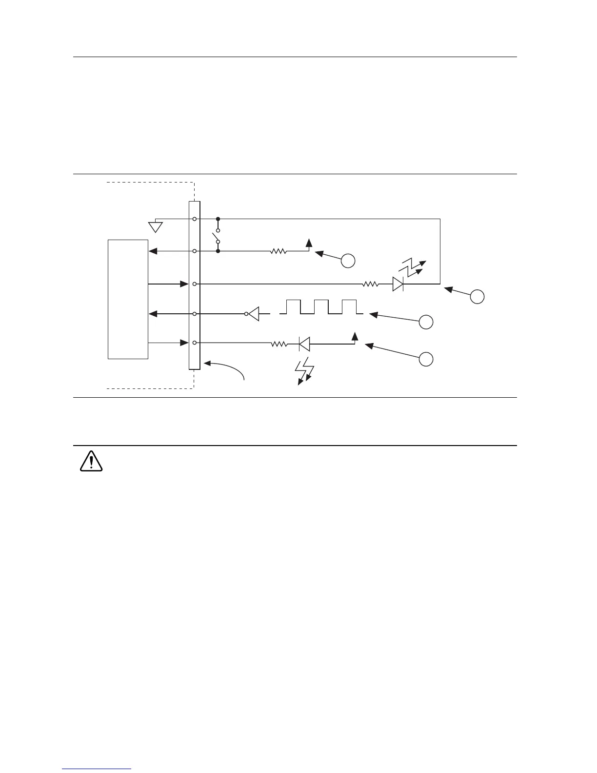
Figure 8 shows P0.<0..3> connected to signals configured as digital inputs and digital outputs.
Figure 8. Example of Connecting a Load
Caution Exceeding the maximum input voltage ratings or maximum output
ratings, which are listed in the NI USB-6000 Specifications document, can damage
the device and the computer. National Instruments is not liable for any damage
resulting from such signal connections.
Power-On States
At system startup and reset, the hardware sets all DIO lines to high-impedance inputs. The DAQ
device does not drive the signal high or low. Each line has a weak pull-down resistor connected
to it.
Source/Sink Information
The default configuration of the digital I/O ports is active drive, allowing 3.3 V operation, with
a source/sink current limit of ±4 mA.
1 P0.0 configured as a digital input receiving a 0 V or 5 V signal from a switch
2 P0.1 configured as an active drive digital output driving an LED
3 P0.2 configured as a digital input receiving a TTL signal
4 P0.3 configured as an open collector digital output driving an LED
Switch
I/O Connector
D GND
P0.0
P0.1
P0.2
P0.3
+5 V
+5 V
LED
LED
4
3
2
NI USB-6000
1


 To Next Page