© National Instruments | 5-5
X Series User Manual
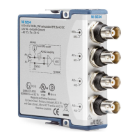
Connecting Analog Output Signals
AO <0..3> are the voltage output signals for analog output channels 0, 1, 2, and 3. AO GND is
the ground reference for AO <0..3>.
Figure 5-2 shows how to make analog output connections to the device.
Figure 5-2. Analog Output Connections
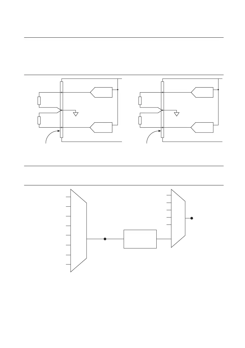
Analog Output Timing Signals
Figure 5-3 summarizes all of the timing options provided by the analog output timing engine.
Figure 5-3. Analog Output Timing Options
X Series devices feature the following analog output (waveform generation) timing signals:
• AO Start Trigger Signal
*
• AO Pause Trigger Signal
*
• AO Sample Clock Signal
*
• AO Sample Clock Timebase Signal
Load
Load
V OUT
V OUT
+
–
+
–
AO GND
AO 3
Analog Output Channels
AO 2
Channel 3
Connector 1 (AI 16– 31)
Channel 2
X Series Device
Load
Load
V OUT
V OUT
+
–
+
–
AO GND
AO 1
Analog Output Channels
X Series Device
AO 0
Channel 1
Channel 0
Connector 0 (AI 0 –15)
PFI, RT
SI
PXI_STA R
Analog Comparison
Event
20 MHz Timebase
100 kHz Timebase
PXI_CLK10
Programmable
Clock
Divider
AO Sample Clock
Timebase
PFI, RTSI
PXI_STA R
Analog Comparison Event
Ctr n Internal Output
100 MHz Timebase
DSTAR <A..B>
DSTAR <A..B>
AO Sample Clock
 Loading...