7-14 | ni.com
Chapter 7 Counters
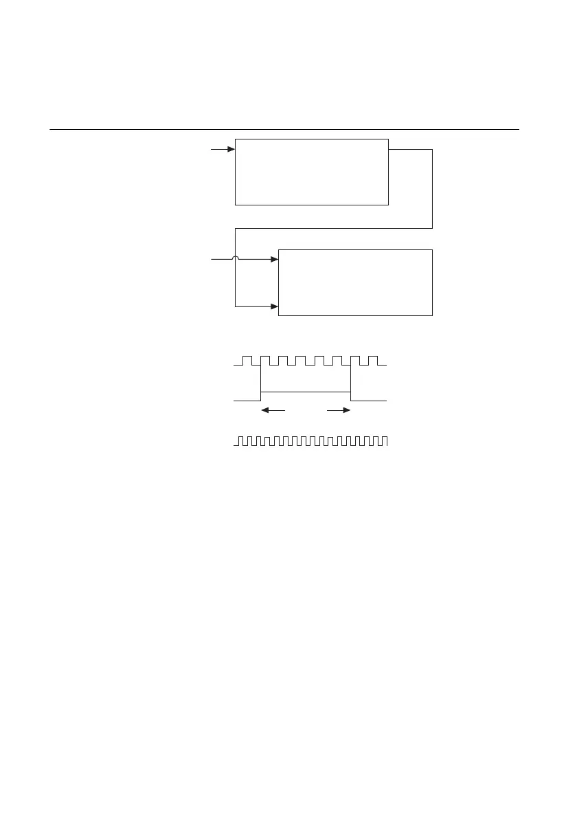
You can route the signal to measure to the Source input of Counter 0, as shown in Figure 7-14.
Assume this signal to measure has frequency fx. NI-DAQmx automatically configures
Counter 0 to generate a single pulse that is the width of N periods of the source input signal.
Figure 7-14. Large Range of Frequencies with Two Counters
NI-DAQmx then routes the Counter 0 Internal Output signal to the gate of Counter 1. You can
then route a signal of known frequency (fk) as a counter timebase to the Counter 1 Source input.
NI-DAQmx configures Counter 1 to perform a single pulse-width measurement. Suppose the
result is that the pulse width is J periods of the fk clock.
From Counter 0, the length of the pulse is N/fx. From Counter 1, the length of the same pulse is
J/fk. Therefore, the frequency of fx is given by fx = fk *(N/J).
Sample Clocked Buffered Frequency Measurement
Sample clocked buffered point frequency measurements can either be a single frequency
measurement or an average between sample clocks. Use CI.Freq.EnableAveraging to set the
behavior. For buffered frequency, the default is True. For hardware-timed single point
(HWTSP), the default is False.
Source Out
Counter 0
Source
Gate
Out
Counter 1
Signal to
Measure (fx)
Signal of Known
Frequency (fk)
CTR_0_SOURCE
(Signal to Measure)
CTR_0_OUT
(CTR_1_GATE)
CTR_1_SOURCE
Interval
to Measure
0123 … N
 Loading...