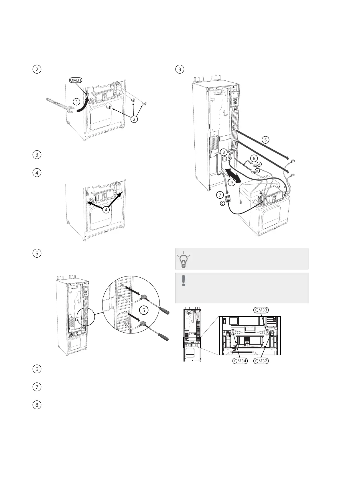
Pull off the lock catches.
Disconnect the pipe connection at the shut-off valve
(QM31).
Remove the two screws.
Remove the connections from the base card (AA2)
using a screwdriver.
Disconnect the connectors (A) and (B) from the un-
derside of the base card cabinet.
Disconnect the connector (C) from the immersion
heater circuit board (AA1) using a screwdriver.
Disconnect the connector (D) from the joint circuit
board (AA100).
Carefully pull out the cooling module.
TIP
The cooling module is installed in reverse order.
NOTE
At reinstallation, the supplied O-rings must re-
place the existing ones at the connections to
the heat pump (see image).
F1245Chapter 7 | Component replacement52
 Loading...


