1x230 V 5-12 kW
3x400 V 5 kW
3x400 V 6-12 kW
3x230 V 6-10 kW
3x230 V 12 kW
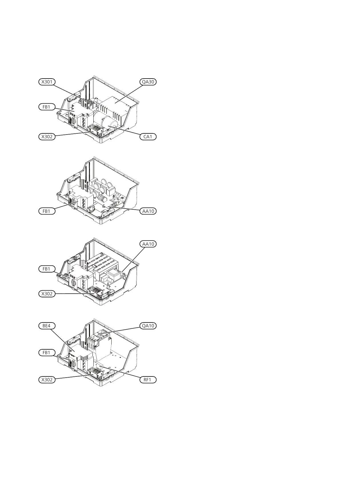
Electrical components
Soft-start cardAA10
Phase sequence monitor (3-phase)BE4
CapacitorCA1
Motor cut-out**FB1
Contactor, compressorQA10
Soft-starterQA30
Suppression capacitorRF1
Terminal blockX301
Terminal blockX302
** 1x230 V, 3x230 V 6-10 kW, 3x400V 5 kW has auxiliary switch
for motor cut-out.
Designations in component locations according to
standard IEC 81346-1 and 81346-2.
F1245Chapter 2 | The heat pump design8
 Loading...


