Electrical connection
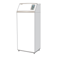
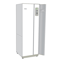
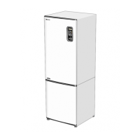
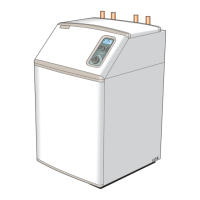
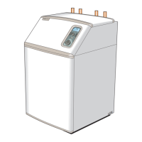
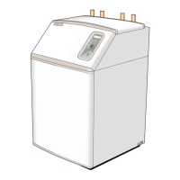
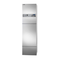
FIGHTER 1320
16
NOTE!
Electrical installation and servicing
must be carried out under the
supervision of a qualified electrician
in accordance with the
stipulations in force.
The cable for incoming power shall enter from the rear
as set out in the figure.
The sensor inputs and communication connection are
of the type SELV. Sensors cables must not be rout-
ed together with power cables. Cables may be
taken out from the rear of the heat pump.
Electrical installation
See respective Description of functions for connection
of external sensors.
For example, for the flow sensor (FG), return sensor
(RG), outdoor sensor (UG) see Description of func-
tions - Basic functions > Heat production. For the hot
water sensor (VVG), see Description of functions -
Basic functions > Hot water production.
Connection of
external sensors
NOTE!
The sensor and communication cables must not
be routed close to the power cable.
This applies to all external sensors and
all communication cables.
When cable conduit is used for the outdoor
sensor this should be sealed to prevent
condensation in the outdoor sensor capsule.

 Loading...
