Connections
TERMINAL BLOCKS
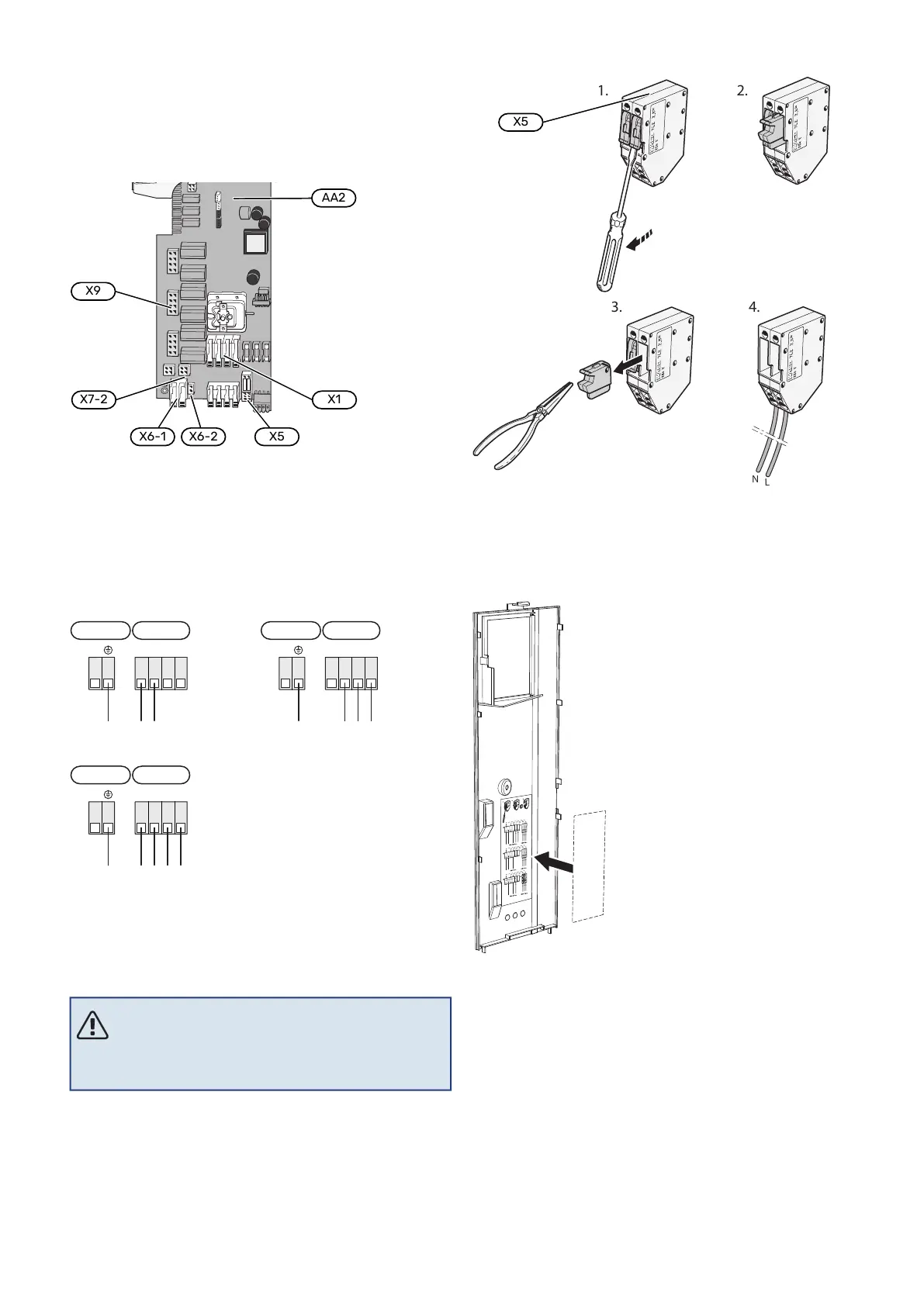
The following terminal blocks are used on the base board
(AA2).
-X29
-X28
1 0-5V
2 +5V
3 AUX1
4 AUX2
5 AUX3
6 AUX4
7 AUX5
8 AUX6
9 AUX7
10 AUX8
11 AUX9
12 BT25
1
1
2
3
2
3
4
5
6
7
8
9
10
11
12
GND
+12V
B
A
OT+
OT−
0-5V
PWM0
PWM1
CPU
EXT COM
INT COM
ERROR
POWER
+5V
GND
BE1
BE2
BE3
K10
-X27
NO
O
NC
AUX-RELAY
13 BT50
14 BT1
-X30
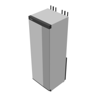
POWER CONNECTION
Supply voltage
Enclosed cable for incoming supply electricity is connected
to terminal block X1 and X6-1 on the PCB (AA2).
Connection 3x230 V
AA2-X1
PE (L2) L1 L2 L3
1 2 3 4
AA2-X6-1
Connection 1x230 V
AA2-X1
PE N L (L) (L)
1 2 3 4
AA2-X6-1
Connection 3x400 V
AA2-X1
AA2-X6-1
PE N L1 L2 L3
1 2 3 4
External control voltage for the control
system
If the control system is to be powered separately from the
other components in the heat pump (e.g. for tariff control),
a separate operating cable must be connected.
NOTE
During service, all supply circuits must be discon-
nected.
Remove the bridges from terminal block X5.
Control voltage (230 V ~ 50Hz) connects to AA2:X5:N, X5:L
and X6-2 (PE).
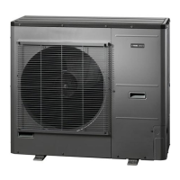
Enclosed label
The enclosed label is placed on the electrical connection’s
cover.
Tariff control
If the voltage to the immersion heater and/or compressor
is lost for a period, "Tariff blocking" must be selected at the
same time via the selectable inputs, see section "Selectable
inputs".
NIBE S1256Chapter 5 | Electrical connections22