English – 3
English
SbS input For normally open contacts (closing of the contact triggers the Step-by-Step (SbS) command)
Stop input For normally open contacts and/or for 8.2 kΩ constant resistance, or normally closed contacts
with self-recognition of the “normal” status (any variation from the memorised status triggers the
Stop command)
Radio aerial input 50Ω for RG58 or similar type of cable
Max. cable length Mains power supply: 30 m; inputs/outputs: 20 m with antenna cable preferably shorter than 5
m (observe the warnings regarding minimum gauge and type of cables)
Ambient operating temperature -20°C ... +55°C
Assembly -
Protection rating IP44
Dimensions / weight 248 x 216 h 305 mm / 7.5 kg 248 x 216 h 305 mm / 7.5 kg
Possibility of remote control Using ECCO5... transmitters, the control unit is able to receive one or more of the following
commands: Step-by-Step (SbS) - Partial Open - Open Only - Close Only
Memory capacity Up to 250 transmitters, if memorised in Mode 1 – 250 keys, if memorised in Mode 2
ECCO5... transmitter range From 50 to 100 m. This range can vary if there are obstacles or electromagnetic disturbances
and is also affected by the position of the receiving aerial incorporated in the ashing light
Programmable functions Operation with “semi-automatic” or “automatic” cycle
“Slow” or “fast” motor speeds
Pause time during “complete cycle”, selectable from 10, 20, 40, 60 seconds
Pedestrian opening type selectable in 4 modes
Obstacle detection system motor force, 4 selectable levels
Step-by-Step (SbS) command operation selectable in 4 modes
Self-programmed functions Self-detection of devices connected to the ECSBus output
Self-detection of the type of Stop device (NO or NC contact or 8.2 kΩ resistor)
Self-detection of the gate length and calculation of the deceleration points
ote: in order to improve its products, NICE S.p.A. reserves the right to modify their technical specications at any time without prior notice. In any case,
the manufacturer guarantees their functionality and suitability for their intended use. Note: all technical specications refer to a temperature of 20°C.
3.4 - PRE-INSTALLATION WORKS
Consult Fig. 3 to dene the approximate installation position of each device mounted on the system; the various elements are positioned according to
a standard and customary layout.
Get all the tools and equipment required to complete the job; check that they are in good condition and that they conform to the local safety provisions.
Laying of electrical cables:
01. Observe Fig. 3 to understand how the various devices should be connected to the control unit and which terminals should be used for each con-
nection.
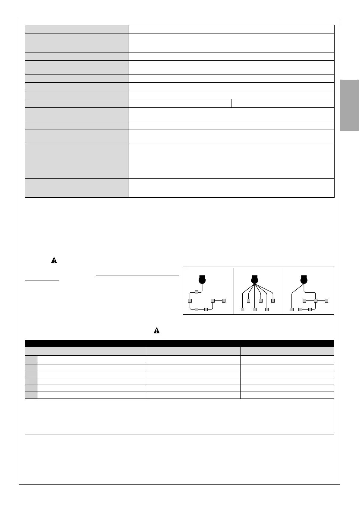
Only devices adopting the same technology can be connected to the ECSBus.
The ECSBus system allows for connecting multiple devices together using,
between one device and the next, a single “bus” cable, with 2 internal elec-
trical conductors.
The connection between the devices can have a “cascade”, a “star” or a
“mixed” conguration, between the rst two.
cascade star combined
02. Observe Fig. 3 to understand how to position the electrical cables in the environment (it is advisable to draw on paper a similar layout, adapting it
to the relevant requirements).
03. Read Table 1 to determine the type of cables to be used:
each cable must not exceed the stated maximum length.
TABLE 1 - Types of electrical cables (see Fig. 3)
Connection Type of cable Maximum admissible length
A 230 VAC 50/60 Hz power supply 3 x 1.5 mm
2
(not supplied) 30 m *
B Flash ashing light output 2 x 0.5 mm
2
20 m
C Radio aerial RG58-type shielded cable 20 m (recommended < 5 m)
D ECSBus Input / Output 2 x 0.5 mm
2
20 m **
E Stop input 2 x 0.5 mm
2
20 m **
F SbS (Step-by-Step) input 2 x 0.5 mm
2
20 m **
* it is possible to use a power cable longer than 30 m, provided that it has a larger gauge (for example, 3 x 2.5 mm
2
) and is equipped with an
earthing device, near the automation.
** For the ECSBus cables and the Stop and SbS inputs, it is also possible to use a single cable with multiple internal conductors, to group multi-
ple connections: for example, the Stop and SbS inputs can be connected to the KS100 selector with a cable measuring 4 x 0.5 mm
2
.
CAUTION! – The cables used must be suited to the installation environment; for example a cable of type H03VV-F for indoor envi-
ronments, or type H07RN-F for outdoor environments.