ENGLISH – 13
EN
2. release the buttons when LEDs “L3” and “L4” start ash-
ing quickly (after roughly 3 seconds)
3. press
g
4. LED “L1” ashes: position 0 of M1
– to command and bring motor 1 to position “0” (“Fig-
ure 15”): press and hold the
f
o
h
button. Once this position is reached, release the but-
ton to stop the manoeuvre
– to memorise the position, press and hold the
g
button for at least 3 seconds then release it (after 2 sec-
onds LED “L1” will remain lit and after the
g
button is released, LED “L2” will start ashing)
5. LED “L2” ashes: position 0 of M2
– to command and bring motor 2 to position “0” (“Fig-
ure 15”): press and hold the
f
o
h
button. Once this position is reached, release the but-
ton to stop the manoeuvre
– to memorise the position, press and hold the
g
button for at least 3 seconds then release it (after 2 sec-
onds LED “L2” will remain lit and after the
g
button is released, LED “L5” will start ashing)
6. LED “L5” ashes: position A of M2 (congurable only af-
ter tyhe opening position is acquired)
– to command and bring motor 2 to position “A” (“Fig-
ure 15”): press and hold the
f
o
h
button. Once this position is reached, release the but-
ton to stop the manoeuvre
– to memorise the position, press and hold the
g
button for at least 3 seconds then release it (after 2 sec-
onds LED “L5” will remain lit and after the
g
button is released, LED “L6” will start ashing)
7. LED “L6” ashes: position A of M1 (congurable only af-
ter tyhe opening position is acquired)
– to command and bring motor 1 to position “A” (“Fig-
ure 15”): press and hold the
f
o
h
button. Once this position is reached, release the but-
ton to stop the manoeuvre
– to memorise the position, press and hold the
g
button for at least 3 seconds then release it (after 2 sec-
onds LED “L6” will remain lit and after the
g
button is released, LED “L7” will start ashing)
8. LED “L7” ashes: position 1 of M2
– to command and bring motor 2 to position “1” (“Fig-
ure 15”): press and hold the
f
o
h
button. Once this position is reached, release the but-
ton to stop the manoeuvre
– to memorise the position, press and hold the
g
button for at least 3 seconds then release it (after 2 sec-
onds LED “L7” will remain lit and after the
g
button is released, LED “L8” will start ashing)
9. LED “L8” ashes: position 1 of M1
– to command and bring motor 1 to position “1” (“Fig-
ure 15”): press and hold the
f
o
h
button. Once this position is reached, release the but-
ton to stop the manoeuvre
– to memorise the position, press and hold the
g
button for at least 3 seconds then release it (after 2 sec-
onds LED “L8” will remain lit until the
g
button
is released).
l
When LEDs "L1..L8" ash, to shift between LEDs
simply press the
f
or
h
button brief-
ly (the LED will ash to signal the current position).
a
On systems with a single motor, programme the po-
sitions relative to motor 2 only: LEDs L2 (0 of M2),
L5 (A of M2) and L7 (1 of M2).
4.8.3 Learning in mixed mode
m
The user has maximum 10 seconds to press the
buttons consecutively during the learning proce-
dure. After this time, the procedure terminates au-
tomatically and memorises the changes made up to
that time.
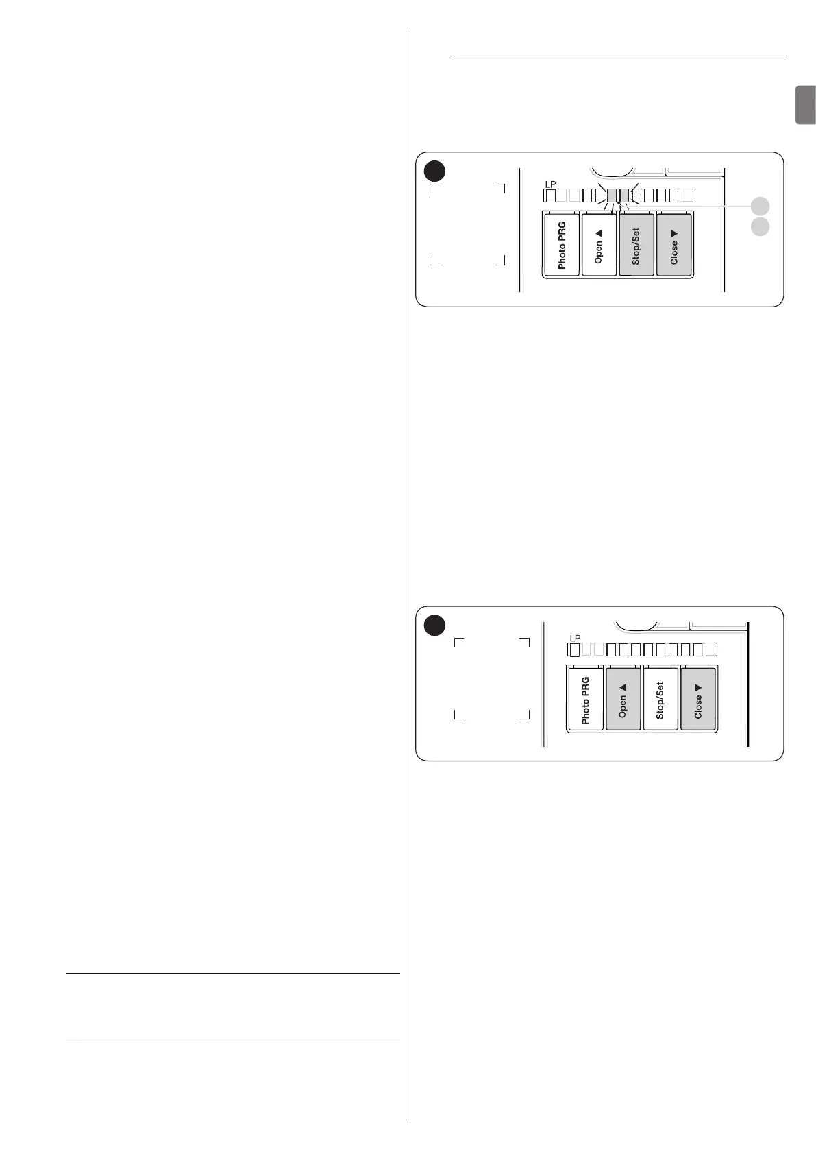
L5 L6 L7 L8L4L3L2L1
L3
L4
18
To effect the learning procedure in mixed mode:
1. run the self-learning procedure in automatic mode as de-
scribed under the “Learning in automatic mode” para-
graph
2. simultaneously press and hold the and
g
buttons
h
3. release the buttons when LED “L1” starts ashing
4. briey press the
f
o
h
button to shift the
ashing LED (L1…L8) to the position to be programmed
5. proceed for each individual position, as described in the “
Learning in manual mode” paragraph
6. repeat this last operation for all the other positions to be
modied.
4.9 CHECKING THE GATE MOVEMENT
At the end of the learning phase, we recommend letting the con-
trol unit run a few opening and closing manoeuvres to verify
whether the gate moves correctly and if there are any assembly
and adjustment defects.
L5 L6 L7 L8L4L3L2L1
19
1. To do this:
2. press the
f
button (“Figure 19”). Check that the
acceleration, constant-speed and slowdown phases are
present during the opening manoeuvre. Once the ma-
noeuvre terminates, the gate leaves must stop a few cen-
timetres from the opening mechanical stop
3. press the
h
button (“Figure 19”) and verify that
the acceleration, constant-speed and slowdown phas-
es are present during the closing manoeuvre. Once the
manoeuvre terminates, the gate leaves must be perfectly
closed on the closing mechanical stop
4. check that all the previously adjusted functions have been
learned by the control unit.