ENGLISH – 3
EN
– The manufacturer declines all liability for damages to
property, objects or people resulting from failure to
observe the assembly instructions. In such cases, the
warranty for material defects shall not apply.
– The weighted sound pressure level of the emission A is
lower than 70 dB(A).
– Cleaning and maintenance reserved for the user must
not be carried out by unsupervised children.
– Before intervening on the system (maintenance, clean-
ing), always disconnect the product from the mains
power supply and from any batteries.
– Inspect the system frequently, in particular the cables,
springs and supports to detect any imbalances and
signs of wear or damage. Do not use the product if it
needs to be repaired or adjusted, because defective
installation or incorrect balancing of the automation can
lead to injuries.
– The packing materials of the product must be disposed
of in compliance with local regulations.
PRODUCT DESCRIPTION AND INTENDED USE
2
2 PRODUCT DESCRIPTION AND INTENDED USE
MC800 is an electronic control unit for automating swing gates. The control unit is specially congured for being connected to
devices belonging to the Opera System and to the Bluebus system. Other available accessories include receivers congured with
“SM” connector.
a
Any use of the product other than the intended use described is not allowed!
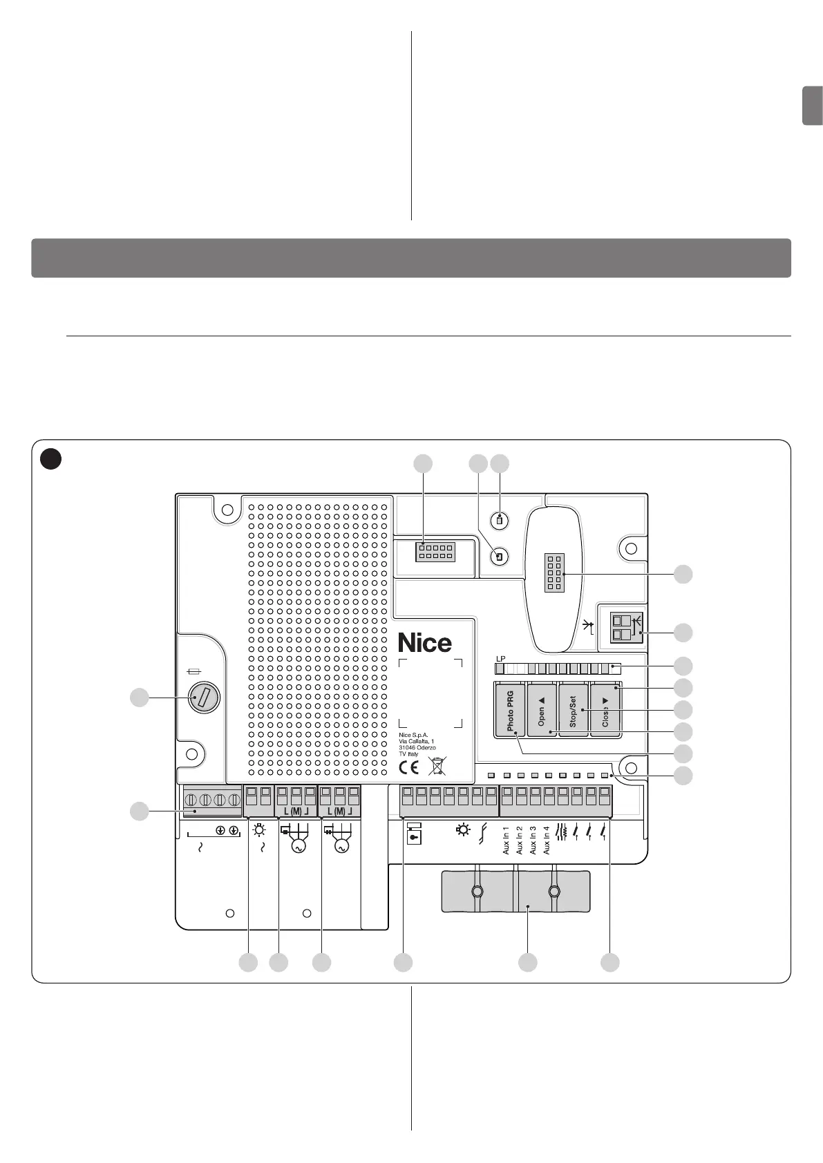
2.1 LIST OF CONTROL UNIT PARTS
The control unit consists of an electronic command and control board housed and protected in the box. “Figure 1” shows the main
parts making up the board.
IBT4N
M1
M2
L5 L6 L7 L8L4L3L2L1
5A F
L N
Power Supply
120/230V
120/230V
50/60 Hz
M2M1
Flash
Common
0V
EL
OGI
Bluebus
2
Close
Open
SbS
Stop
FLASH 1 2 3 4 5 6 7 8 9 10 11 12 13 14 15
A
B
I
O
N
M
L
K
P
J
1
A Protection fuse (5A F)
B Mains power inputs terminal
C FLASH output terminal (120/230 V)
D Motor 1 output terminal
E Motor 2 output terminal
F OUTPUTS terminal block (low-voltage)
G Cable clamps for fastening the power connections
H INPUTS terminal block (low-voltage)
I Inputs/outputs status LEDs
J Button for operation with relay photocells
K “Open” command and control unit programming button
L “Stop/Set” command and control unit programming button
M “Close” command and control unit programming button
N Control unit status visualisation LED
O Radio antenna terminal (accessory)
P “SM” quick connector for radio receiver (accessory)
Q Motor M1 status LED
R Motor M2 status LED
S IBT4N interface connector (accessory)