20 – ENGLISH
EN
Table 10
SIGNALS OF LED (L1..L4) (“FIGURE 22”)
Status Meaning Possible solution
LEDs L1 - L2
Slow ashing
Change in the number of devices
connected to the “BlueBus” or
learning of the device not executed.
It is necessary to run the device learning procedure (refer to the
“Learning of connected devices” paragraph)
LEDs L3 - L4
Slow ashing
The positions of the mechanical
stops were never learned or after the
mechanical stop learning procedure,
the dip-switch conguration changed.
It is necessary to run the device learning procedure (refer to the
“Learning of connected devices” paragraph)
FURTHER INFORMATION
(Accessories)
8
8 FURTHER DETAILS (Accessories)
8.1 CONNECTING AN SM-TYPE RADIO RECEIVER
The control unit has a slot for mounting radio receivers with SM
connector (optional accessories), which can be used to remote-
ly control the control unit through transmitters that intervene on
the unit’s inputs.
f
Before installing a receiver, disconnect the power
supply to the control unit.
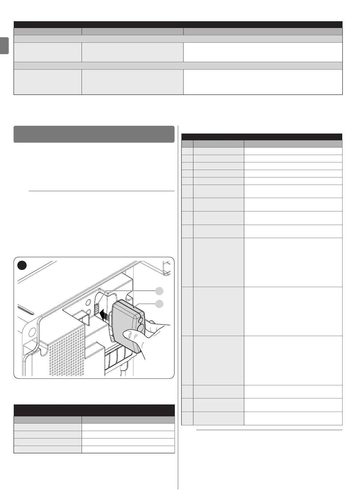
To install a receiver (“Figure 23”):
1. remove the cover of the control unit’s containment box
2. insert the receiver (A) in the appropriate slot (B) on the
control unit’s electronic board
3. put the cover of the control unit’s containment box back
on.
At this stage, the control unit can be powered again.
A
B
23
“Table 11” and “Table 12” show the “Receiver outputs” and the
“Control unit inputs” associated with each.
Table 11
SMXI / SMXIS OR OXI / OXIFM / OXIT / OXITFM IN MODE 1 OR MODE
2
Receiver output Control unit input
Output No. 1
“SbS” (Step-by-Step) command
Output No. 2
“Partial opening 1” command
Output No. 3
“Open” command
Output No. 4
“Close” command
Table 12
OXI / OXIFM /OXIT / OXITFM IN MODE 2 EXTENDED
No. Command Description
1 Step-by-Step
“SbS” (Step-by-Step) command
2 Partial opening 1
“Partial opening 1” command
3 Open
“Open” command
4 Close
“Close” command
5 Stop
Stops the manoeuvre
6
Condominium
Step-by-Step
Command in condominium mode
7
High priority Step-
by-Step
Commands also with the automation
locked or the commands enabled
8 Partial open 2
Partial opening (the M2 gate leaf opens
to 1/2 the full length)
9 Partial open 3
Partial open (the two gate leaves open
to 1/2 the full length)
10
Opens and locks
the automation
Triggers an opening manoeuvre
and, once this terminates, locks the
automation; the control unit will not
accept any command other than “High
priority Step-by-Step” and automation
“Unlock”, or (only from Oview) the
following commands: “Unlock and
close” and “Unlock and open”
11
Closes and locks
the automation
Triggers a closing manoeuvre and,
once this terminates, locks the
automation; the control unit will not
accept any command other than “High
priority Step-by-Step” and automation
“Unlock”, or (only from Oview) the
following commands: “Unlock and
close” and “Unlock and open”
12 Lock automation
Triggers the stoppage of the
manoeuvre and locks the automation;
the control unit will not accept any
command other than “High priority
Step-by-Step” and automation
“Unlock”, or (only from Oview) the
following commands: “Unlock and
close” and “Unlock and open”
13
Release
automation
Triggers unlocking of the automation
and restores normal operation
14
On Timer
Courtesy light
The courtesy light output switches on
with timer-based switching off
15
On-Off
Courtesy light
The courtesy light output switches on
and off in Step-by-step mode
l
For further information, consult the specic manual
of the receiver.