14
3
3
Thin Walled
Tube Gate
Gate
Bracket
1” x 6” Wood Reinforcement
Panel
Gate
Gate
Bracket
Wood or Metal
Reinforcement
(not supplied)
Mounting Plate
Created for
Decorative Gate
(required but not
supplied)
Remove excess
bolt length with
hacksaw or bolt cutters
FRONT VIEW
SIDE VIEW
Reinforcement and Gate Bracket Mounting
Mufer Clamp
(not supplied)
Gate
Bracket
4
1
2
1" Min. - Pinch-Point Clearance
Top View
1" Min.
4”–13"
2
1
Closed
Position
Open
Position
stroke
2
1
5
5
L
V
O
F
G
T
S
S
E
B
N
N
3
Thin Walled
Tube Gate
Gate
Bracket
1” x 6” Wood Reinforcement
Panel
Gate
Gate
Bracket
Wood or Metal
Reinforcement
(not supplied)
Mounting Plate
Created for
Decorative Gate
(required but not
supplied)
Remove excess
bolt length with
hacksaw or bolt cutters
FRONT VIEW
SIDE VIEW
Reinforcement and Gate Bracket Mounting
Mufer Clamp
(not supplied)
Gate
Bracket
4
1
2
1" Min. - Pinch-Point Clearance
Top View
1" Min.
4”–13"
2
1
Closed
Position
Open
Position
stroke
2
1
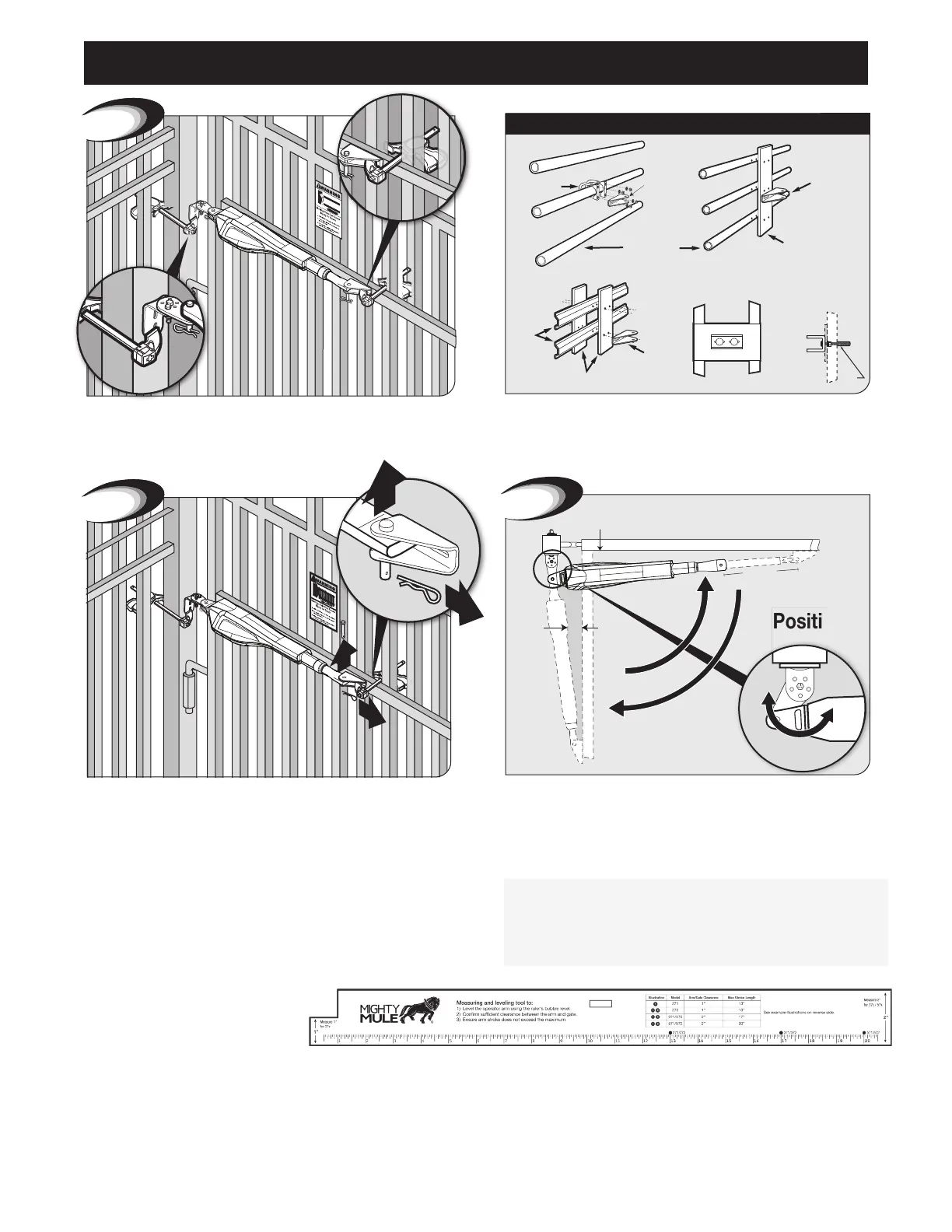
With Gate in OPEN position, using clamps, secure operator to
gate post and center cross member of gate.
Recommended reinforcement and gate bracket mounting
examples.
Swing gate and operator arm to the CLOSED position-check
clearance/binding by inspecting alignment. Arm stroke should be a
maximum of 13”.
TIP: Turning the pivot bracket over gives more
hole alignment options for the post pivot bracket assembly.
IMPORTANT:
Without adequate clearance and alignment, the
gate operator will NOT function correctly. To ensure proper
installation, use the included Installation Ruler to install the
operator and the bracket.
Remove clevis pin from the gate bracket and support loose
operator.
Gate Operator Installation
Installation Ruler