10 – ENGLISH
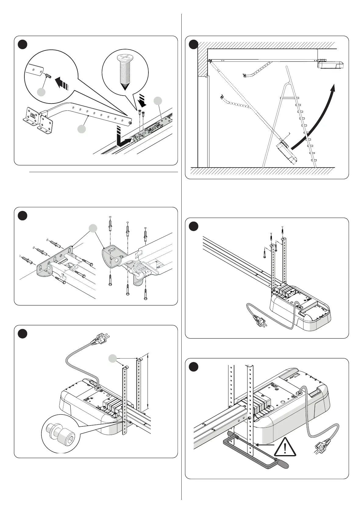
14. mount the pin (O) onto the drawbar (L)
15. attach the drawbar to the motor carriage ( P)
16. lock the bracket in place using the two screws (“Figure 16")
O
L
P
16
a
Verify that the distances chosen for installing the product
are compatible with the limit distances (see “Figure 7").
17. fasten the wall mounting bracket (J) to the wall above the door or
to the ceiling (“Figure 17")
J
17
18. use two screws to fasten the ceiling mounting brackets (Q) while
observing the desired distance (“Figure 18")
Q
18
19. using a ladder, lift the gearmotor until the brackets touch the ceiling
20. mark the drilling points and then put the gearmotor back on the
ground (“Figure 19")
19
21. drill through the marked points
22. using a ladder, lift the gearmotor until the brackets rest against the
drilled holes
23. fasten them using screws and plugs suited to the relevant material
(“Figure 20")
20
24. ensure that the guide lies perfectly horizontal, then cut off the ex-
cess section of the brackets with a saw (“Figure 21")
21