Nikon Communication Interface Manual
!!!CAUTION!!!
- Connection to the instrument side must follow the pin assignment above.
Misconnection may result in malfunctioning.
- By connecting RS-232C communication signal from external device and GND
to the pin #1,#2, and #5 on instrument side, the external device can be
download/upload data to the instrument.
- Electricity can be provided through pin #3 and #5 on the instrument, even if
the clip-on battery is mounted. The rated apparent power is DC7.2-11V (4.5
V to 5.2 V for
Nivo only), Max 1A. Not to use the out-of-range power; it may
result in malfunctioning.
3-2. Connecter on external devices (in case of connection cable)
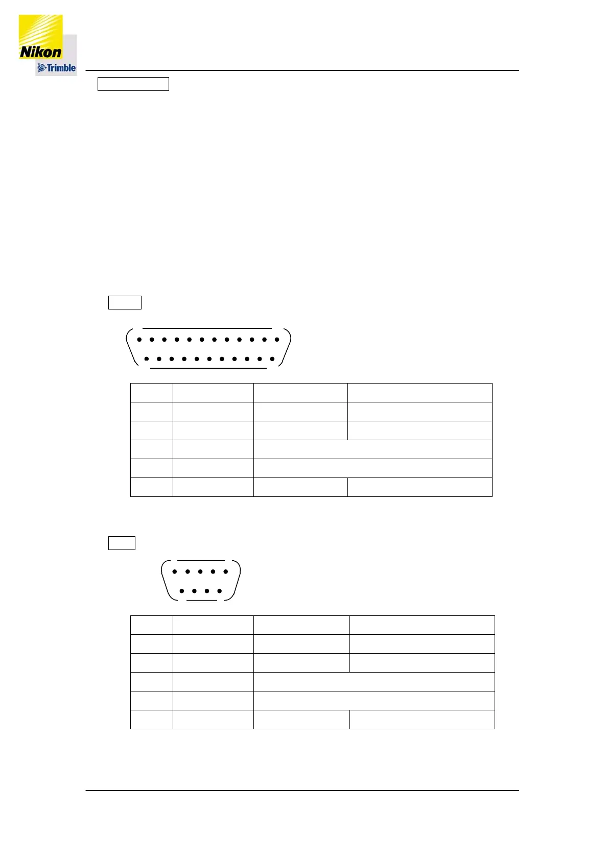
25 Pin
13
1
14
25
lignment looking at the pin side of the plug
No. Symbol Signal name Direction
2 TXD
Sending data* Instrument
ÅExternal device
3 RXD
Receiving data* Instrument
ÆExternal device
4, 5 CTS, RTS (connected inside)
6, 20 DSR, DTR (connected inside)
7 GND
Ground
N/A
* Name of the signal is from its action looking at the external device.
9 Pin
9
6
1
5
lignment looking at the hole side of the plug
No. Symbol Signal name Direction
2 RXD
Receiving data* Instrument
ÆExternal device
3 TXD
Sending data* Instrument
ÅExternal device
4, 6 DSR, DTR (connected inside)
7, 8 CTS, RTS (connected inside)
5 GND
Ground
N/A
* Name of the signal is from its action looking at the external device.
P4/34