Nikon Communication Interface Manual
1. Introduction
This manual explains how to connect Nikon Total Stations and external devices by
serial interface. About hardware and communication software necessary to the
connection are briefly described as well.
2. Interface system
The interface is directed by RS-232C. External devices must have a RS-232C port.
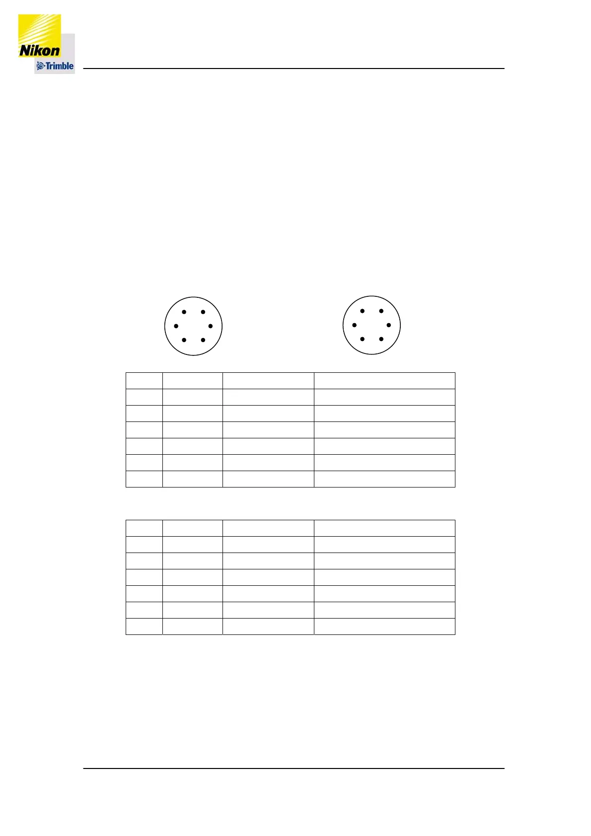
3. Connecter
3-1. Interface connecter
Cable side: HR10A-7R-6P Instrument side: HR10A-7R-6S
(Hirose Electric Co.) (Hirose Electric Co.)
HRS
6
4
5
1
3
2
HRS
1
3
2
6
4
5
<Pin assignments other than Nivo >
No. Symbol Signal name Direction
1 RXD Receiving data* InstrumentÅExternal device
2 TXD Sending data* InstrumentÆExternal device
3 V Power** N/A
4 NC Not in use N/A
5 GND Ground N/A
6 NC Not in use N/A
<Pin assignment for Nivo only>
No. Symbol Signal name Direction
1 RXD Receiving data* InstrumentÅExternal device
2 TXD Sending data* InstrumentÆExternal device
3 NC Not in use N/A
4 V Power** N/A
5 GND Ground N/A
6 NC Not in use N/A
* Name of the signal is from its action looking at the instrument.
** “Power” is a connecter to provide electricity to the instrument. It has nothing to do
with the communication.
(RXD) (TXD)
High level input voltage: 2.4V≦ High level output voltage: 5~15V/3.5~5.0V
Low level input voltage: 0.6V≧ Low level output voltage: -15~-5V/0~1.5V
P3/34