3 Microscopy
1-2 Modulation Contrast (NAMC) Microscopy
E-20
4
Orient the slit diaphragm.
Orient the slit diaphragm so that it properly
overlaps the modulator (focal plane pattern) on the
NAMC objective.
(1) Place the 10x NAMC objective (NAMC1) in the
optical path.
(2) Slide the NAMC slider to place the NAMC1 slit
diaphragm in the optical path.
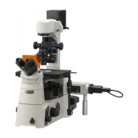
(3) Taking care not to alter the position of the
diopter adjustment ring, remove one eyepiece
from the eyepiece tube and insert a centering
telescope in its place.
(4) Holding down the flange of the centering
telescope, turn the eyepiece of the centering
telescope and focus on the objective
modulator (focal plane pattern) and slit
diaphragm image.
(5) Taking care not to alter the position of the
correction ring on the objective (if any), turn
the modulator ring on the objective to orient
the modulator pattern in the direction in
which you wish to apply contrast.
Be sure at this time, to closely observe where
the slit diaphragm image is located versus the
modulator pattern.
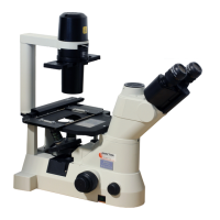
(6) Remove the NAMC1 slit diaphragm from the
optical path. Then, using a hexagonal
screwdriver, press one of the grooves in the
slit diaphragm’s circumference and rotate the
diaphragm so that the lengthwise direction of
the slit image becomes parallel to the
modulator’s G area. (Re-insert the NAMC1 slit
diaphragm in the optical path to check
whether or not the two are parallel. For fine
adjustment, turn the modulator ring.)
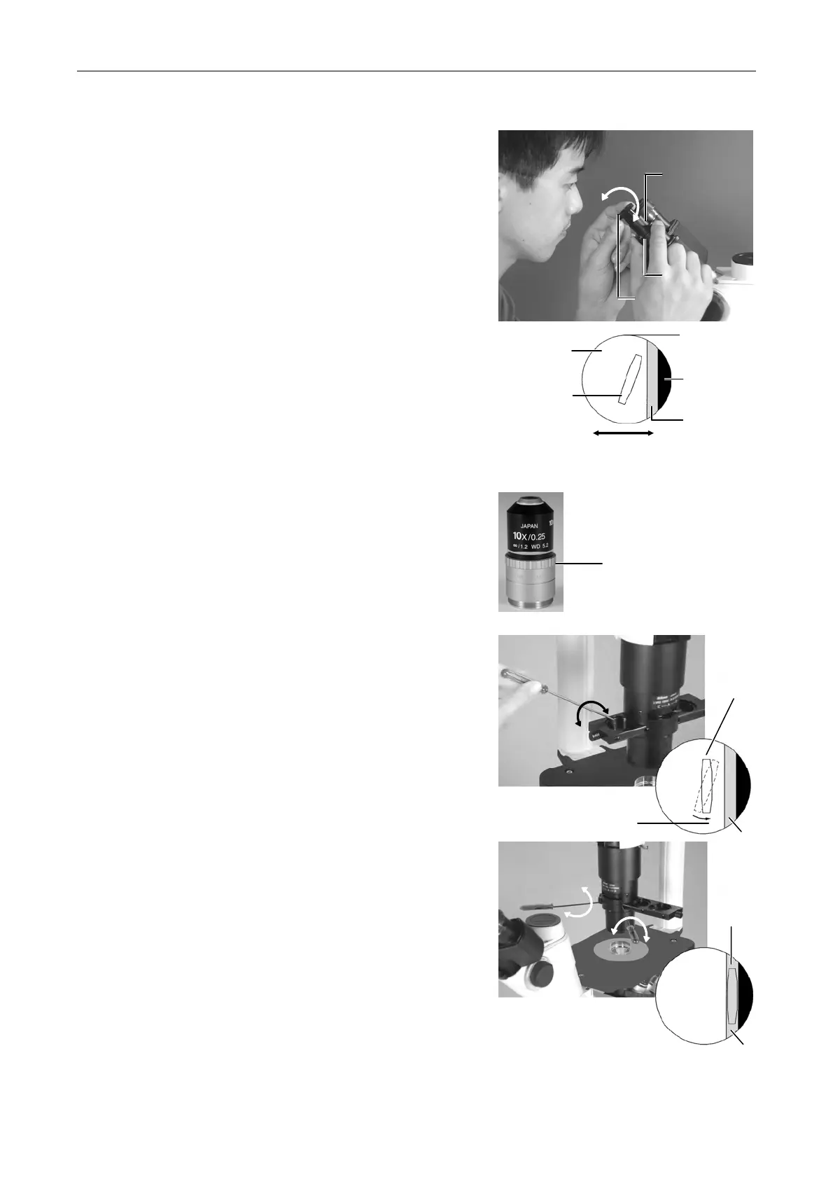
(7) Insert two hexagonal screwdrivers into the
centering holes of the NAMC slider. Then,
while looking through the centering telescope,
adjust so that the slit diaphragm image
perfectly overlaps the modulator’s G area.
(8) If you are using an objective with an NAMC
code other than NAMC1, place that objective
and the slit diaphragm having the same NAMC
code as that objective in the optical path and
orient them in the same manner described
above.
Centering
telescope
Flange
Eyepiece
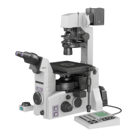
Modulator ring
Parallel to G area.
Slit image
G
G
Slit image
Correctly adjusted
modulator and slit
diaphragm image
NAMC objective
Bright area (B)
Slit diaphragm
image
Exit pupil of
the objective
Dark area (D)
G
ay area (G)
he contrast is attained in
the direction of the arrow.
The modulator and slit diaphragm image.