18 - FORM NO. 56043071 CMAX
™
28/34ST / I-MAX
™
28/32C, BA 750/850ST, BA 750C
SOLUTION SYSTEM
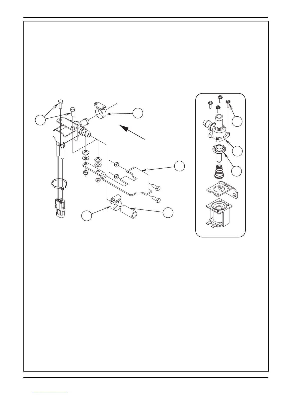
SOLENOID VALVE REMOVAL
1 Drain the solution tank or put the Flow Control Valve Knob (A) (shown in Figure 1) in the full off position to prevent solution loss.
2 Remove the lower left side chassis panel (held in place by 3 screws) and the left side scrub brush skirt assembly from the machine.
3 See Figure 3. Unplug the L1 solenoid valve wire assembly connection from the machine harness.
4 Loosen both the inlet and outlet Hose Clamps (E) and (F) that secure the hoses to the valve body.
5 Separate (pry) the solution outlet hose off from its valve body barbed fitting.
6 Remove the (2) Hex Screws (G) that secure the valve to the Mount Bracket (H), then pull the valve body to the front separating it from the
solution inlet Hose (I), completing the part removal.
FRONT
E
H
I
F
G
Assembly
L
K
J
FIGURE 3
SOLENOID VALVE DISASSEMBLY AND CLEANING
1 Remove the solenoid valve. See the Solenoid Valve Removal section for instructions.
2 See Figure 3. Remove the (4) (J) Screws and disassemble the valve (be careful not to lose any internal parts).
3 Thoroughly wash dirt from block (K) and diaphragm (L).
4 After reassembling, test the solenoid valve for proper operation.
SOLUTION FILTER REMOVAL
1 Drain the solution tank using the solution drain hose or put the flow control valve knob in the full off position to prevent solution loss.
2 See Figure 4A or 4B. Loosen the (2) Hose Clamps (M) and pry off the inlet solution hose from the filter head hose barb fitting.
3 Remove the (2) Hose Clamps (N) that secure the filter housing to the Mount Bracket (H), then pull the valve body to the rear separating it
from the solution outlet hose, completing the part removal.
SOLUTION FLOW CONTROL VALVE REMOVAL
1 Drain the solution tank using the drain hose.
2 See Figure 4A or 4B. Loosen the (2) Hose Clamps (O) and (P) and pry off inlet solution Hose (Q) from the flow control valve.
3 Remove the Philips head Screw (R) (using a short handled screwdriver) that secures the operator solution adjustment rod (S) to the ball
valve arm and separate.
4 Remove the (2) Nuts (T) & Screws (U) that secure the valve Mount Bracket (V) to the chassis. Then pull the valve and bracket to the rear
separating the valve from the solution outlet Hose (W), completing the part removal.

 Loading...