ELECTRICAL SYSTEM
64 - FORM NO. 56043071 CMAX
™
28/34ST / I-MAX
™
28/32C, BA 750/850ST, BA 750C
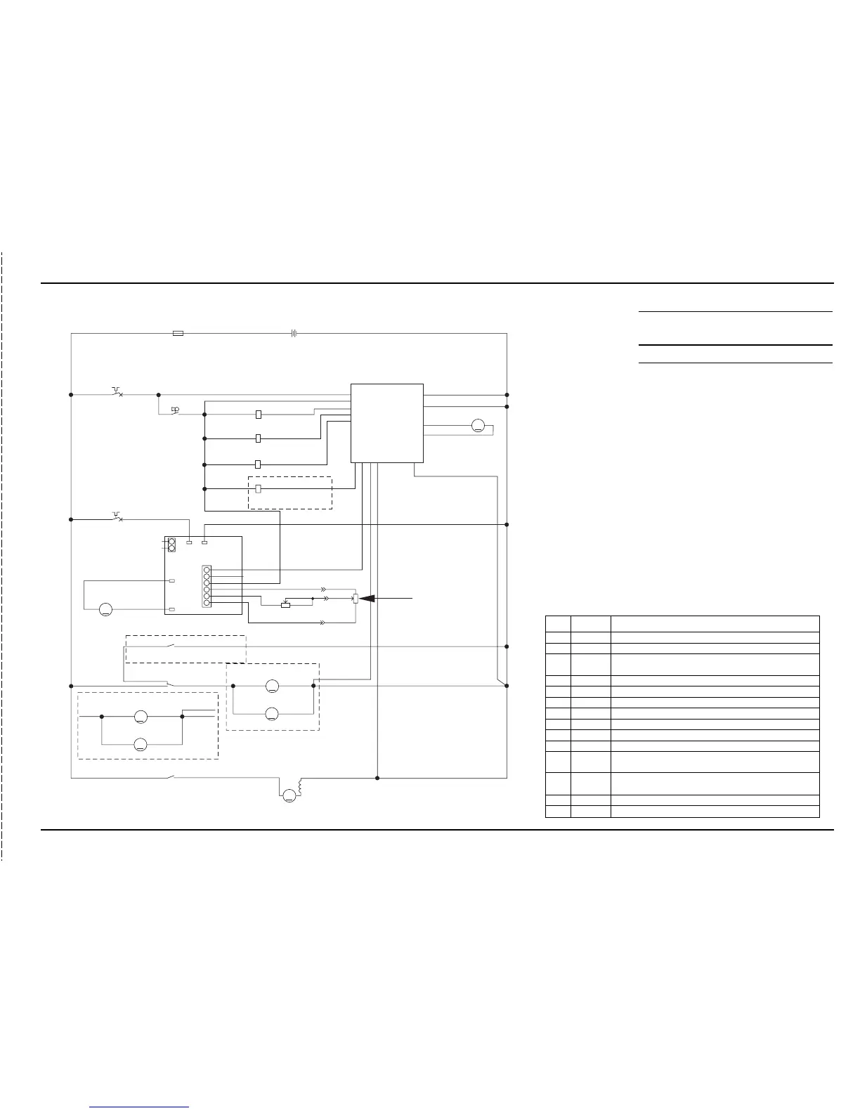
WIRING DIAGRAM / SCHEMATIC
Item Description
A1 Control PCB Assy
A2 Control, DC Curtis
BT Batteries*
F1 Fuse, 150 Amp
F2 Circuit Breaker 5 Amp (Control Circuit)
F3 Circuit Breaker 30 Amp (Wheel Drive)
K1 Contactor, (Brush Motor) (Standard-SPST / Option-SPDT)
K2 Contactor, (Vac Motor) (SPST)
K3 Relay, (Brush Remove/Optional)
L1 Solution Solenoid Valve
M1 Motor (Wheel Drive)
M2 Motor (Left Brush)
M3 Motor (Right Brush)
M4 Motor (Vacuum)
M5 Actuator, Motor (Brush Lift)
R1 Potentiometer, 5K (Forward-Reverse / Throttle)
R2 Potentiometer, 25K (Speed Limit)
S3 Switch, Key (Main Power)
RED
FUSE, 150A
F1
1
2
RED
BT1
+
-
BATTERY
24VDC OR 36VDC
BLK
BLK
A1
CONTROL BOARD
RED
GRN
F2
1
2
CIRCUIT BREAKER
5 AMP
S3
SWITCH
SPST KEY
GRN
BLK/WHT
4
13
B-2
B-3
M5
M
VIO/YEL
WHT/GRN
MOTOR
BRUSH ACTUATOR
14
B+2
1
B+1
BRN
5BRUSH CONTACTOR
VIO/BLK
BRN
K1
COIL. BRUSH MOTOR CONTACTOR
6 VACUUM CONTACTOR
7SOLUTION
BRN
K2
BLK/YEL
COIL. VAC MOTOR CONTACTOR
BRN
L1
1
2
RED/GRN
COIL. SOLUTION SOLENOID
K3
BRN ORN/BLK
RELAY, BRUSH REMOVE
OPTIONAL
11
12
BRUSH ACTUATOR-2
BRUSH ACTUATOR-1
REMOVE RELAY
FOR/REV
BRUSH MOTOR
VAC MOTOR
B-1
GRA/BLK
2
9
8
3
10
GRA/BLK
BLK
RED
F3
1
2
CIRCUIT BREAKER
30 AMP
WHT/YEL
BRN
YEL
YEL
ORN
ORN
BLK
BLK
WHT/GRA
WHT/GRA
BLK
M3
M
M2
M
MOTOR, RIGHT BRUSH
MOTOR, LEFT BRUSH
POLARITY FOR DISC BRUSHES
+
-
+
-
12
M4
M
MOTOR, VAC
BLU
RED
K2
R1
POT. 5K OHM THROTTLE
POLARITY FOR CYLINDRICAL BRUSHES
+
-
+
-
M3
M
M2
M
MOTOR, RIGHT BRUSH
MOTOR, LEFT BRUSH
WHT/GRA
BLK
WHT
WHT
RED
K1
K3
BLU/WHT
CONTACT, BRUSH REMOVE
OPTIONAL
A2
1208 SPEED CONTROLLER
M1
M
MOTOR, WHEEL DRIVE
+
-
BRN/BLK
YEL/RED
B-
(T2)
B+
(T1)
B+
B-
P2
(T3)
M1
(T4)
M2
+ WHEN
FORWARD
P1
1
2
1
2
3
4
5
6
OUTPUT
OUTPUT
KEYSWITCH
REVERSE
WIPER
FORWARD
+
-
VIO
BRN/WHT
GRN/YEL
1
3
2
POT. 25K OHM SPEED LIMIT
1
2
2
3
1
RED/BLK
GRA
R2
A1 Control Board Pin Detail
Pin # Wire Color Controller Pin Description & Function
1Brn Battery (+) key switch input (KSI) powers up controller.
2 Gra/Blk Battery ground input (-) to controller.
3 Yel
A2 speed control auxiliary driver input (-) activates all auto scrub
functions.
4Blk Battery ground (-) circuit input for all solenoid coils.
5 Vio/Blk Controller (-) circuit output to the K1 brush motor solenoid.
6 Blk/Yel Controller (-) circuit output to the K2 Vacuum motor solenoid.
7 Red/Grn Controller (-) circuit output to the L1 solution solenoid.
8Wht/Gra Brush motor current sense wire (+) shunt circuit input to controller.
9Orn Vacuum motor current sense wire (+) shunt circuit input to controller.
10 Orn/Blk Controller (-) circuit output to the K3 brush remove solenoid (Opt).
11 Vio/Yel
Polarity reversing (+ or -) circuit output from the controller to the
brush lift actuator motor.
12 Wht/Grn
Polarity reversing (+ or -) circuit output from the controller to the
brush lift actuator motor.
13 Blk/Wht Battery ground (-) circuit input for brush lift actuator motor.
14 Grn Battery (+) circuit input for brush lift actuator motor.

 Loading...