14 - FORM NO. 56043071 CMAX
™
28/34ST / I-MAX
™
28/32C, BA 750/850ST, BA 750C
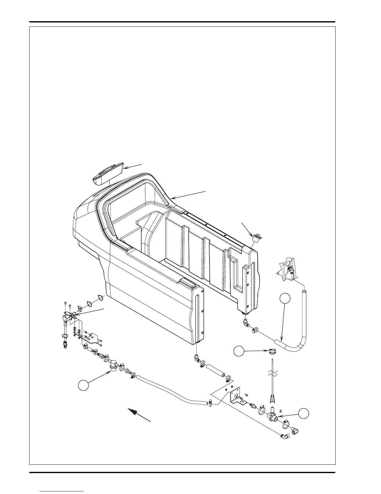
SOLUTION SYSTEM
FRONT
A
B
Fill Opening (Front)
Fill Opening (Rear)
(L1)
Electrical
Solenoid
Valve
Solution Tank
C
D
FUNCTIONAL OVERVIEW
The CMAX
™
28ST, BA 750ST and BA 850ST models have a solution tank fill capacity of 24-gallons (90 liters). The I-MAX
™
28C/32C, BA 750C
and CMAX
™
34ST models tank capacities are 30-gallons (114 liters). All models use two tank fill openings one located in the front and another
in the rear, which offers ease of filling. Plumbed into the main solution control valve hose outlet is a serviceable solution filter, to keep debris from
entering the solenoid valve. Also fitted to the tank is a flexible hose used to indicate the solution level and to drain the tank for system maintenance.
See Figure 1*. The solution system uses (2) valves to regulate the amount of solution dispensed onto the floor. The knob (A) located on the control
panel operates the main solution valve (B) that controls the needed flow volume demand to the scrub brushes. The (L1) electrical solenoid valve
stops and starts the solution flow to the scrub brushes see electrical diagram. The electrical circuit that turns on (energizes) the solenoid coil is
activated through the (A1) control panel’s solution switch button and the (A2) operation wheel drive controller assembly. Note: See the Know Your
Machine section in this manual for a complete explanation of the solution operation modes.
During normal machine scrubbing the solution system’s Auto Mode is selected and works in conjunction with the wheel drive speed controller and
the (A1) main controller’s scrub system outputs to turn On & Off the (L1) solenoid valve. The solution will flow to the scrub brushes when the main
flow control valve is open, the scrub deck is lowered and the handle drive paddle (box) is pushed or pulled into Fwd or Rev. Note: When the solution
On/Off button is turned Off, no flow can occur regardless of the manual flow control valve being On, drive control paddle activated and the scrub
deck down.
FIGURE 1
*Note: Figure 1 shows the solution components of the CMAX
™
28ST, BA 750ST and BA 850ST. Similar components are found on the I-MAX
™
28C/32C, BA 750C and CMAX
™
34ST.

 Loading...