For HYDAC gas valve version 4, screw on
valve seal cap “G” torquing to 30 Nm (22
lb-ft), and valve protection cap “H” (where
applicable); hand tighten.
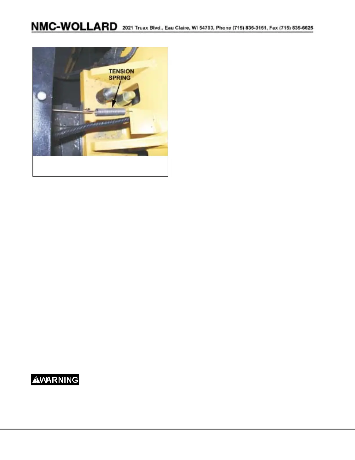
3.11 ADJUST POSITION SENSOR
With the wheels parked straight ahead, both
axle directions indicators should point to C
(Center). If the indicators require adjustment,
position wheels straight ahead. Stop engine.
Turn ignition switch to IGN but do not start
engine. On the driver’s side on top of the
front wheel hub, move the position sensor
tension spring in the holes on the anchor
bracket until the front axle indicates aligns C
(Center). Adjust the rear wheel hub position
indicator the same to align the rear axle direc
-
tion indicator. See Figure 3-6.
3.12 GUIDELINES FOR REPAIRING THE
TRACTOR
Before attempting any re
-
pairs on the tractor, know the safety pre
-
cautions located in the front part of this
manual.
The following are general instructions for
the removal, disassembly, cleaning, in
-
spection, reassembly, and installation of
tractor components within the capabilities
of the using organization. Common shop
practices are not described. Use the ex
-
ploded views in Section 10.
3.12.1 Special Tools
There are no special tools required for this
tractor. Common automotive shop tools
are all that is required to service the trac
-
tor.
3.12.2 Removal and Disassembly
Removal and disassembly should be per-
formed using the exploded views in Chap-
ter 10. Special instructions are noted in the
appropriate text. Disassemble components
only to the extent necessary to do repairs.
3.12.3 Cleaning
When cleaning, keep related parts to-
gether so reassembly is easier. Valves,
pistons, sleeves and other internal parts
that have close tolerance fits in mating
bores should be cleaned individually to
prevent surface scoring and marking. Spe
-
cial cleaning instructions are given where
required.
3.12.3.1 Proper Cleaning Solvent
Unless otherwise specified, cleaning
should be done using dry cleaning solvent,
Federal Specification P-D-680. This can be
applied with clean cloths or used as an im
-
mersion solution for small parts.
NOTE: Do not apply the cleaning solvent
to wiring or electrical parts except to re
-
move foreign materials from housings.
3.12.3.2 Using Compressed Air
PAGE 3-14 PREVENTIVE MAINTENANCE
JULY 31, 2007
M200 MB4 Tow Tractor Manual No. 42975
FIGURE 3-6. ADJUST POSITION
SENSOR


 To Next Page