1
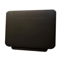
Place the indoor ONT unit on a flat surface, such as a desk or shelf.
Note: The G-2426G-A cannot be stacked with another ONT or with other equipment. The
ONT mounting requirements are:
• allow a minimum 100 mm clearance above the top cover
• allow a minimum 50 mm clearance from the side vents
• do not place any heat source directly above the top cover or below the bottom cover
2
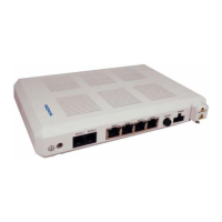
Review the connection locations, as shown in Figure 5-1, “G-2426G-A ONT connections”
(p. 56)
.
3
Connect the Ethernet cables to the RJ-45 ports.
4
Route the POTS cable directly to the RJ-11 port as per local practices.
Figure 5-1 G-2426G-A ONT connections
ON/OFF
RESET
WLAN
POWER
LAN4LAN3LAN2LAN1TEL2TEL1
USB
LEDWPS
36176
POTS port
(RJ-11)
Ethernet ports (4)
(RJ-45)
Power
Reset
button
Wi-Fi
security/
on/off buttons
On/off
button
USB
port
Install a G-2426G-A indoor ONT
Procedure
7368 ISAM ONT
Draft Draft
September 2020
Issue 1 57
Nokia – Proprietary and Confidential
Use pursuant to applicable agreements
3FE-XXXXX-AAAA-TCZZA
 Loading...