WWW.NORAC.CA
PRECISIONDEFINED
Page24
Visitwww.solutions.norac.caformoresystem
installationandtroubleshootinginfo.
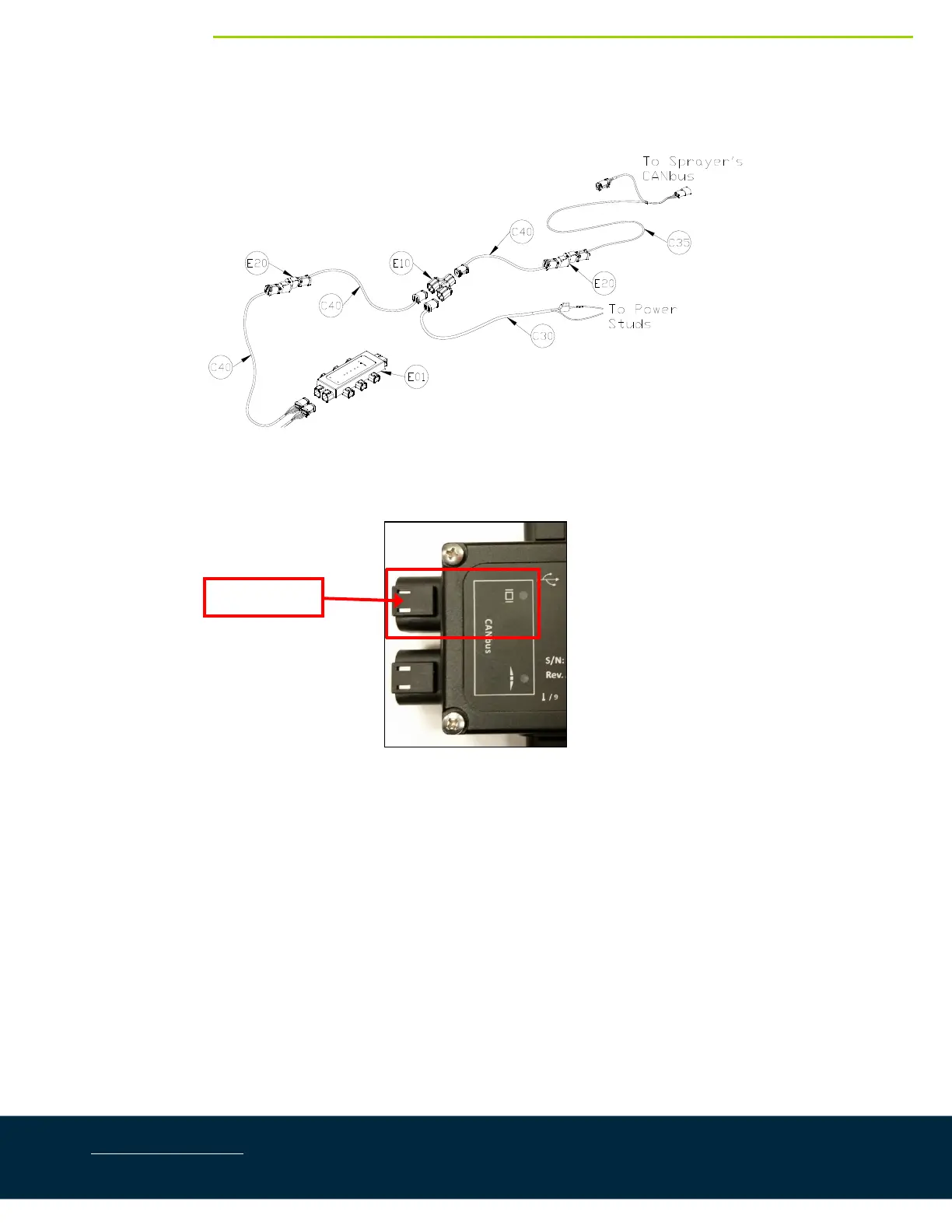
7.4. DisplayCablingConnections( 2014‐2017)
Figure37:DisplayCablingOverview(2014‐2017)
1. ConnectcableC40tothe6‐pindisplaybusconnectorontheHCM1(Figure32).
Figure38:DisplayBusLocation
2. Connect cable C40 to cable C40 with a 2‐way coupler with terminator (E20).The 2‐way coupler with
terminatorisWHITE.
3. ConnectcableC40toa3‐waycoupler(E10).
4. Connectthepowercable(C30)tothe3‐waycoupler(E10).ConnecttheotherendofC30tothepower
studsattherearofthemachine(Figure39).
DisplayBus