Antenna Offsets
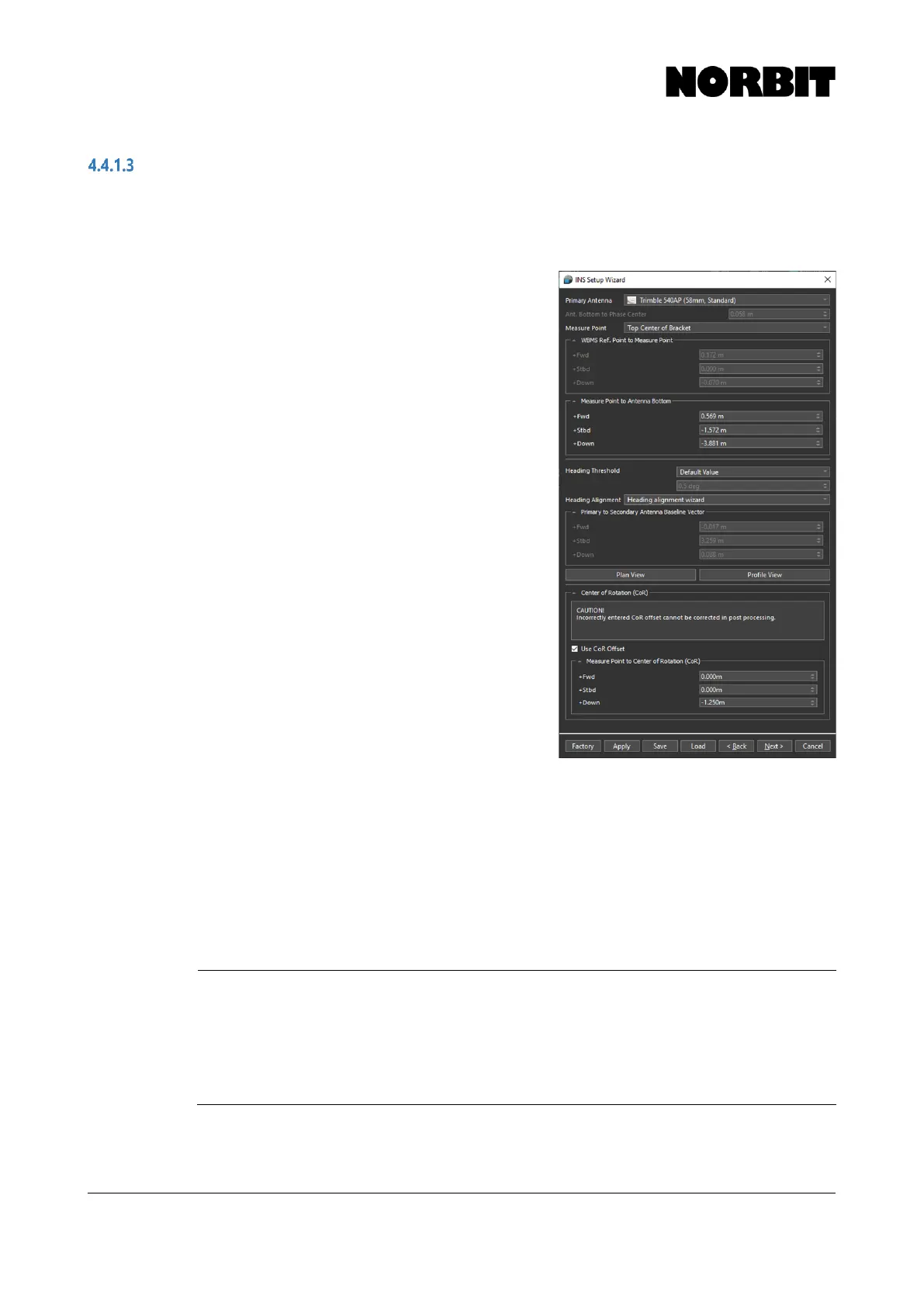
Offsets related to the GNSS antennas are found on the second page of the setup wizard. Select the
Primary Antenna model, which in most cases will be Trimble 540AP, to ensure that the correct
phase center offset is applied.
Select the Measure Point to define a convenient
reference point from which to measure the primary
antenna offset. Top Center of Bracket should be
selected; however, a Custom point may also be defined.
The system uses the entered antenna offset, together
with the offset from WBMS Ref. Point to Measure Point,
to relate the antenna position to the sonar.
Carefully measure the distance from Measure Point to
Antenna Bottom and enter the correct values, bearing
in mind the sign convention (positive down).
Should a positive value be entered for the down offset, a
warning message alerts users that a positive value
places the sonar above the GNSS antennas. The user is
prompted to verify that the correct offset has been
applied. If a special mounting arrangement is employed
and a positive number is correct, the warning may be
ignored.
Users can specify the Heading Threshold for the
heading alignment procedure which follows later. The
Default Value (0.5⁰) is suitable in most cases. It may be
necessary to change the threshold, e.g. if operating a
large vessel and aggressive maneuvering is not feasible.
If the heading calibration does not start within 30 minutes,
select Custom and increase the threshold in 0.5⁰
increments until the calibration starts successfully. Every
time a heading alignment is performed, a patch test
should be performed afterwards.
For Heading Alignment method, select Heading Alignment Wizard to populate the fields in
Primary to Secondary Antenna Baseline Vector with zeros initially. Correct values are displayed
after the calibration is complete (described in section 4.4.2). If the antenna baseline vector is already
known, i.e. if it was measured using land survey techniques, the results can be entered manually by
selecting Custom.
Selecting Plan View or Profile View displays a diagram showing the antenna positions with respect
to the WBMS Reference Point. This can be used for a visual check of the system layout/offsets.