Self-Test Diagnostics
The unit’s control module is equipped with a self-test diagnostic
function which can be read using a light emitting diode (LED). To
access the error codes displayed in the control module, you will
need the items in Fig. 3. Refer to Fig. 4 - Fig. 5.5 for diagnostic
instructions.
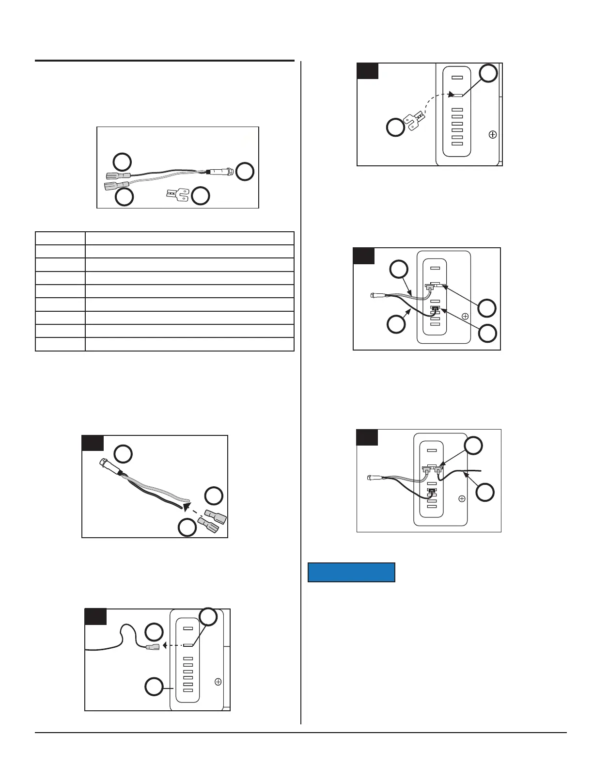
Fig. 3 - LED and connectors
Reference Description
A (1x) 10 mA LED with wire leads
A1 (1x) 1/4 inch push-on female connectors (Black)
A2 (1x) 1/4 inch push-on female connectors (Red)
B 1/4 inch adapter with one (1) female and two (2) male connections
C 12 VDC Input Wire
D 12 VDC Terminal "+"
E Control Module
F Terminal "D"
NOR00000033A
A
B
A2
A1
Connecting the LED
Refer to Fig. 3, and Figs. 4.1-5.5
1. Attach the two (2) female blade connectors
(A1, A2) to the
wire leads of the LED
(A).
Fig. 4.1 - Attach blade connectors
2. On the control module (E), disconnect the 12 VDC input wire
(C) from the "+" terminal (D).
Fig. 4.2 - Disconnect 12 VDC
A
A2
A1
1
_
+
+
F
D
C
P
T
12/24 Vdc
E
C
D
2
Fig. 4.4 - Connect LED
Fig. 4.5 - Connect 12 VDC
Do NOT leave jumpers in place for normal
operation.
Reading the LED
If an error code is activated in the control module (Fig. 5.2, E) and
the LED (Fig. 4, A) is connected, it will fl ash a number of times. The
number of fl ashes will depend on what error was recorded. Each
fl ash will last 1/4 second and after the code is fl ashed there will be
a delay, then the code will repeat.
Write down all error codes; then refer to "Self-Test Diagnostic
Chart" in this section.
NOTICE
3. Connect the blade adapter (B) to the "+" (D) terminal.
Fig. 4.3 - Connect blade adapter
4. Connect the black LED wire (A1) to terminal "D" (F); connect
the red LED wire
(A2) to the one side of blade (B).
5. Connect the 12 VDC input wire
(C) to the other side of adapter
blade
_
+
+
F
D
C
P
T
12/24 Vdc
D
B
3
_
+
+
F
D
C
P
T
12/24 Vdc
A1
F
C
A2
4
DIAGNOSTICS - cont’d.
D
_
+
+
F
D
C
P
T
12/24 Vdc
C
5
SERVICE MANUAL
9
www.norcold.com