NORDAC FLEX (SK 200E ... SK 235E) – Users Manual for Frequency Inverters
154 BU 0200 en-3118
Pos: 36 4 /Anlei tung en/El ektr onik/FU und Star ter/5 . Par ameter/ Par ameter aufli stung (P000 .. .)/P2 00-P2 99/Par amet er P241 – Induktivi taet PM SM @ 0\mod_1327590972170_388.docx @ 8393 @ @ 1
P241 [-01]
[-02]
Inductivity PMSM
(Inductivity PMSM)
S P
0.1 ... 200.0 mH
{ all 20.0 }
The typical asymmetric reluctances of the PMSM are compensated with this parameter. The stator
inductances can be measured by the frequency inverter (P220)
[-01] = d axis (L
d
) [-02] = q axis (L
q
)
Pos: 36 5 /Anlei tung en/El ektr onik/FU und Star ter/5 . Par ameter/ Par ameter aufli stung (P000 .. .)/P2 00-P2 99/Par amet er P243 – Relukt anz win kel IPM SM @ 6\ mod_1417603844346_388.docx @ 191712 @ @ 1
P243 Reluct. angle IPMSM
(Reluctance angle IPMSM)
S P
0 … 30 °
{ 0 }
In addition to the synchronous torque, synchronous motors with embedded
reluctance torque. The reason for this is due to the anisotropy (inequality) between the inductivity in
the d and the q direction. Due to the superimposition of these two torque components, the optimum
efficiency is not at a load angle
of 90°, as with SPMSMs, but rather with larger values. This
additional angle, which can be assumed as 10° for NORD motors, can be taken into account with
this parameter. The smaller the angle, the smaller the reluctance component.
The specific reluctance angle for the motor can be determined as follows:
•
Allow drives with constant load ( > 0.5 M
N
) to run in CFC mode (P300 ≥ 1)
• Gradually increase the reluctance angle (P243) until the current (P719) reaches a minimum
Pos: 36 6 /Anlei tung en/El ektr onik/FU und St art er/5 . Par amet er/ Par amet erau fli st ung (P 000 .. .)/P 200- P299 /Par amet er P244 – Spitzenstrom PMSM @ 0\mod_1327591035576_388.docx @ 8416 @ @ 1
P244 Peak current PMSM
(Peak current PMSM)
S P
0.1 … 1000.0 A
{ 5.0 }
This parameter contains the peak current of a synchronous motor. The value must be obtained
from the motor data sheet.
Pos: 36 7 /Anlei tung en/El ektr onik/FU und Star ter/5 . Par ameter/ Par ameter aufli stung (P000 .. .)/P2 00-P2 99/Par amet er P245 – Pendeldämpfung PMSM VFC @ 6\ mod_1417605252683_388.docx @ 191743 @ @ 1
P245 Osc damping .PMSM VFC
(Oscillation damping PMSM VFC)
S P
5 … 100 %
{ 25 }
In VFC open-loop mode, PMSM motors tend to oscillate due to insufficient intrinsic damping. With
the aid of "oscillation damping" this tendency to oscillate is counteracted by electrical damping.
Pos: 36 8 /Anlei tung en/El ektr onik/FU und Star ter/5 . Par ameter/ Par ameter aufli stung (P000 .. .)/P2 00-P2 99/Par amet er P246 – Masse nträg heit PM SM @ 0\mod_1327591081936_388.docx @ 8439 @ @ 1
P246 Mass inertia PMSM
(Mass inertia PMSM)
S P
0.0 … 1000.0 kg*cm²
{ 5.0 }
The mass inertia of the drive system can be entered in this parameter. For most applications the
default setting is sufficient. However, for highly dynamic systems the actual value should ideally be
entered. The values for the motors can be obtained from the technical data. The portion of the
external centrifugal mass (gear unit, machine) must be calculated or determined experimentally.
Pos: 36 9 /Anlei tung en/El ektr onik/FU und Star ter/5 . Par ameter/ Par ameter aufli stung (P000 .. .)/P2 00-P2 99/Par amet er P247 – Umschal tfreq uenz VFC PMSM @ 6\mod_1417606764814_388.docx @ 191774 @ @ 1
P247
Switch freq.VFC PMSM
(Switchover frequency VFC PMSM)
S P
1 ... 100 %
{ 25 }
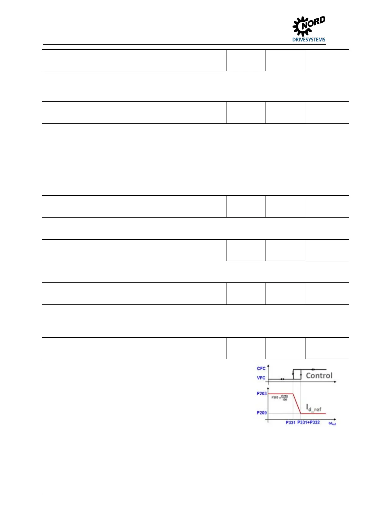
In order to provide a minimum amount of torque
immediately in case of spontaneous load changes, in VFC
mode the setpoint of I
d
(magnetisation current) is controlled
depending on the frequency (field increase mode) The
amount of this additional field current is determined by
parameter (P210). This reduces linearly to the value "zero",
which is reached at the frequency which is gov
(P247). In this case, 100 % corresponds to the rated motor
frequency from (P201).
Pos: 37 0 /Allg emein/ Allg emeing ültig e Mod ule/---------Sei tenumbr uch ko mpakt --------- @ 13\mod_1476369695906_0.docx @ 2265495 @ @ 1
 Loading...


