8 Additional information
BU 0200 en-3118 259
Pos: 728. 6 / Anlei tu ngen /El ektr oni k/F U un d St art er/ 8. Z usa tzin for mati on en/R ed uzier te Aus ga ngsl eist ung /_R eduzi er ter Üb erstr om aufgrund der Ausgangsfrequenz @ 0\mod_1328188934696_388.docx @ 14351 @ 3 @ 1
8.4.3 Reduced overcurrent due to output frequency
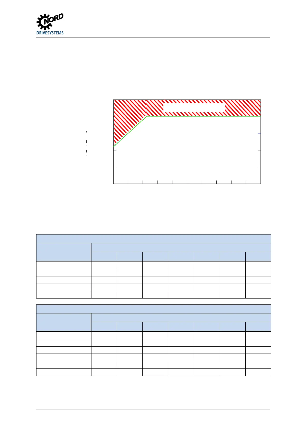
To protect the power unit at low output frequencies (<4.5Hz) a monitoring system is provided, with
which the temperature of the IGBTs (insulated-gate bipolar transistor) due to high current is
determined. In order to prevent current being taken off above the limit shown in the diagram, a pulse
switch-off (P537) with a variable limit is introduced. At a standstill, with 6kHz pulse frequency, current
above 1.1x the nominal current cannot be taken off.
x
f( )
In_ 60s ec
f( )
In_ 1s e c
f( )
f
0
2
4
6
8
10
12
14
16
18
20
0
0.5
1
1.5
2
2.5
The upper limiting values for the various pulse frequencies can be obtained from the following tables.
In all cases, the value (0.1…1.9) which can be set in parameter P537, is limited to the value stated in
the tables according to the pulse frequency. Values below the limit can be set as required.
230V devices: Reduced overload capacity (approx.) due to pulse frequency (P504) and output frequency
Pulse frequency [kHz]
Output frequency [Hz]
4.5 3.0 2.0 1.5 1.0 0.5 0
3...8 200% 170% 150% 140% 130% 120% 110%
14 150% 127% 112% 105% 97% 90% 90%
400V devices: Reduced overload capacity (approx.) due to pulse frequency (P504) and output frequency
Pulse frequency [kHz]
Output frequency [Hz]
4.5 3.0 2.0 1.5 1.0 0.5 0
10 150% 127% 112% 105% 97% 90% 82%
Table 17: Overcurrent relative to pulse and output frequency
Pos: 72 8.7 /A nleitu ngen/ Elektr onik /FU und St art er/ 8. Z usa tzin for mati on en/R ed uzier te Aus ga ngsl eist ung /_R eduzi er ter Ausg ang sst rom aufg ru nd der N etz sp ann ung @ 0\ mod_1328189086271_388.docx @ 14374 @ 3 @ 1
 Loading...


