NORDAC FLEX (SK 200E ... SK 235E) – Users Manual for Frequency Inverters
60 BU 0200 en-3118
Pos: 13 2 /Anlei tung en/El ektr onik/FU und Star ter/2 . Mon tage un d Install atio n/Ele ktrisc her Ans chlus s/SK 1xxE, SK 2 xxE, S K xxxE-FD S/L eist ung stei l/ Elek tris cher An schl uss L eist ungs teil _T eil 0_Ü bers chri ft [ SK 1 xxE, SK 2xx E, -FD S] @ 19\ mod_1511526725283_388.docx @ 2372474 @ 3 @ 1
2.4.2 Electrical connection of power unit
Pos: 13 3 /Anlei tung en/El ektr onik/FU und Star ter/1 . Allg emei nes/Sic herh eits- und Ins tall ations hinwei se un d Warn- Gefahrenhinweise/neu/Warn- und Ge fahrenhinweise/ACHTUNG - EMV – St örung der Umg ebung [SK 1xxE , SK 2xxE , 5xxE] @ 19\mod_1511527115653_388.docx @ 2372510 @ @ 1
EMC Interference to the environment
This device produces high frequency interference, which may make additional suppression measures necessary
in domestic environments ( Section 8.3 "Electromagnetic compatibility (EMC)").
The use of shielded motor cables is essential in order to maintain the specified radio interference suppression
level.
Pos: 13 4 /Anlei tung en/El ektr onik/FU und Star ter/2 . Mon tage un d Install atio n/Ele ktrisc her Anschl uss/SK 1xxE, SK 2xxE, SK xxxE-FDS/Leistung steil/Elektrischer Anschluss Leistungs teil_Teil1 [SK 1xxE, SK 2xxE] @ 7\mod_1434530744023_388.docx @ 226339 @ @ 1
When the device is being connected, please note the following:
1. Ensure that the mains supply provides the correct voltage and is suitable for the current required
( Section 7 "Technical data").
2. Ensure that suitable electrical fuses with the specified nominal current range are installed between
the voltage source and the device.
3. Mains cable connection: to terminals L1-L2/N-L3 and PE (depending on device)
4. Motor connection: to terminals U-V-W
A 4-core motor cable must be used if the device is being wall-mounted As well as U-V-W, PE must
also be connected. If present, in this case the cable shielding must be connected to a large area of
the metallic screw connector of the cable gland.
The use of wire end rings is recommended for connecting to PE.
Information
Connection cables
Only use copper cables with temperature class 80°C or equivalent for connection. Higher temperature classes are
permissible.
When using wiring sleeves, the maximum connection cross-section can be reduced.
Pos: 13 5 /Anlei tung en/El ektr onik/FU und Star ter/2 . Mon tage un d Install atio n/Elektrisch er Anschluss/SK 1xxE, SK 2xxE, SK xxxE-FDS /L eist ung steil /El ekt ris cher An schl uss Lei st ungs teil _Tei l 2 [SK 2x xE] @ 7\mod_1434536283290_388.docx @ 226436 @ @ 1
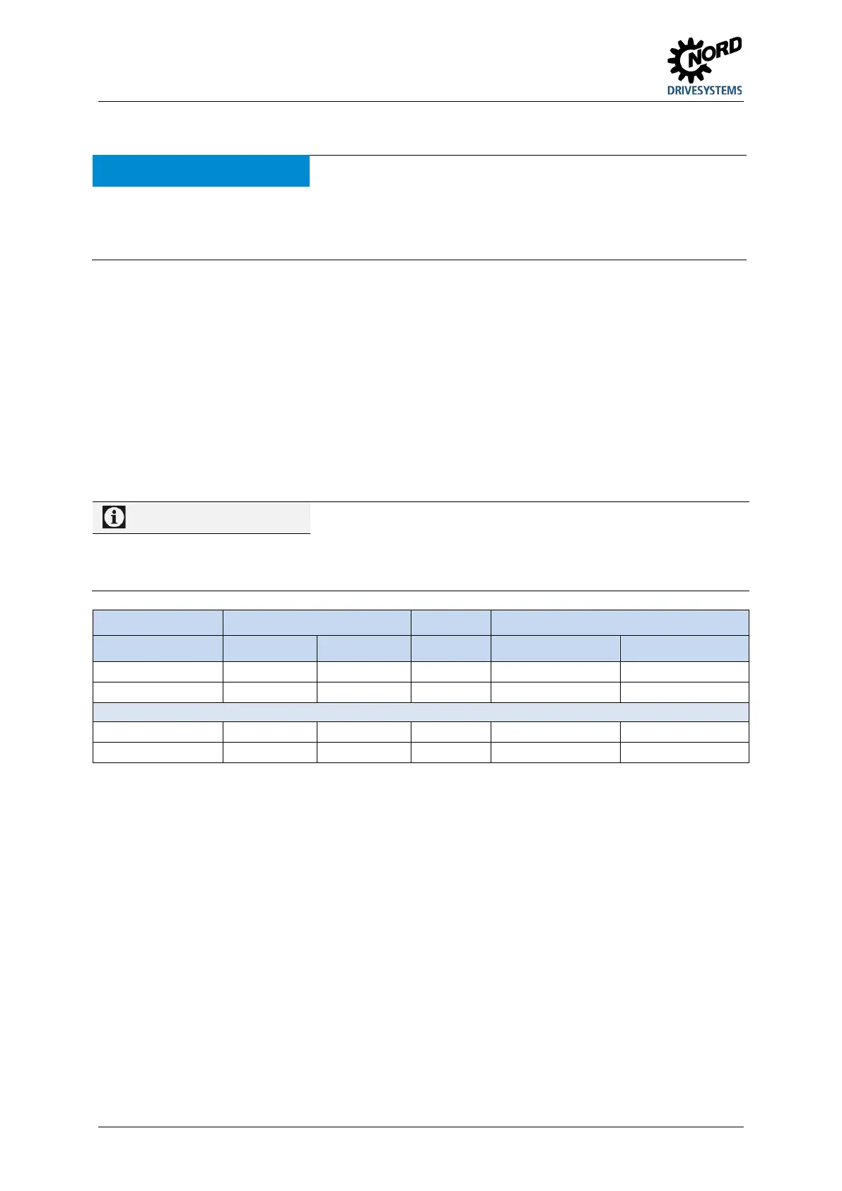
Device Cable Ø [mm²] AWG Tightening torque
Size rigid flexible [Nm] [lb-in]
Electromechanical brake
Table 8: Connection data
Pos: 13 6 /Allg emein/ Allg emeing ültig e Mod ule/---------Sei tenumbr uch ko mpakt --------- @ 13\mod_1476369695906_0.docx @ 2265495 @ @ 1
 Loading...


