Functional Safety – Supplementary manual for series SK 500P
12 BU 0630 en-2020
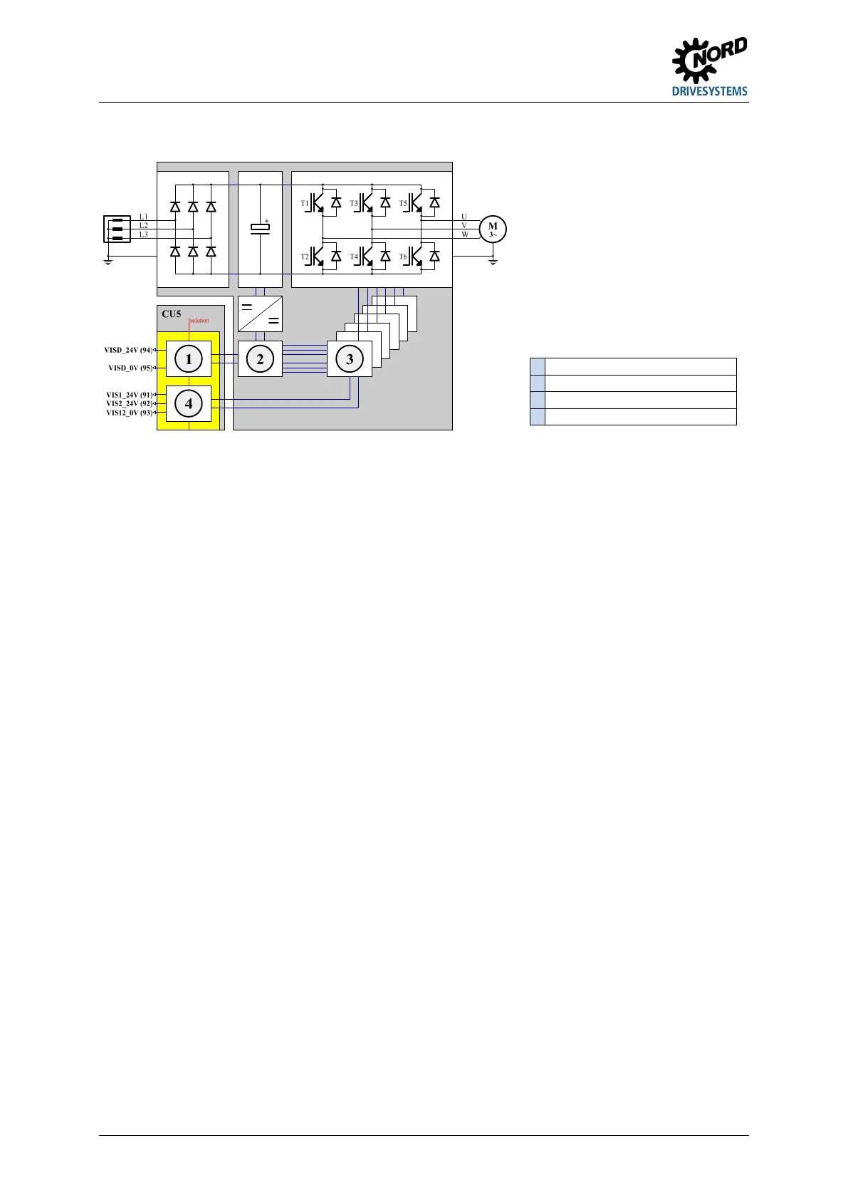
Structure of the Safe Pulse Block for SK 530P, SK 550P with SK CU5-STO or SK CU5-MLT
1 Safety Digital Input
4 Safe Pulse Block
By the use and combination of the safe shut-down methods Safe Pulse Block and/or Safety Digital
Input, the safety-related stop functions STO and SS1, as well as a simple restart block, can be
implemented with various safety and performance levels.
Pos: 46 /A llg em ein/ Allg em eing ülti ge M od ule/ ---------Seite num bruc h kom pak t --------- @ 13 \mod_1476369695906_0.docx @ 2265495 @ @ 1
Pos: 48 /Anlei tunge n/Elek tro nik/Sa fety/ 3. Funkt ions besc hreibu ng/Sic here A bschal tweg e_01 [SK 500P] @ 40\mod_1574333326841_388.docx @ 2577707 @ 2 @ 1
2.2 Safe shut-down methods
Two safe shut-down methods are available for SK 500P series frequency inverters:
1. SK 510P and SK 540P are equipped with a permanently installed safety module.
2. SK 530P and SK 550P can be equipped with optional control terminals. The plug-in modules
SK CU5-SSTO and SK CU5-MLT provide safe shut-down methods.
Both variants provide the following safe shut-down methods:
• Safe Pulse Block
• Safety Digital Input
With the aid of safe shut-down methods, the following safe stop functions can be implemented:
• STO (Safe Torque Off) safely switched off torque
• SS1-t (Safe Stop 1 time controlled)
Pos: 53 /Anlei tunge n/Elek tro nik/Sa fety/ 3. Funkt ions besc hreibu ng/Sic here P ulssp erre _01 [SK 50 0P] @ 44 \mod_1594729516977_388.docx @ 2645437 @ 3 @ 1
2.2.1 Safe Pulse Block
With the aid of an additional DC/DC converter, the Safe Pulse Block generates the supply voltage for
the drivers. For this, the Safe Pulse Block must be provided with a 24 V voltage or two 24 V voltages.
This must be provided as follows:
• SK 510P, SK 540P: 1 x 24 V via contact VIS_24V with reference potential VIS_0V
• SK 530P, SK 550P with SK CU5-STO or SK CU5-MLT: 2 x 24 V via contacts VIS1_24V and
VIS2_24V with common reference potential VIS12_0V
Pos: 55 /Anlei tunge n/Elek tro nik/Sa fety/ 3. Funkt ions besc hreibu ng/Sic here P ulssp erre _02 [SK 50 0P] @ 44 \mod_1594729769814_388.docx @ 2645475 @ @ 1
If this 24 V voltage is switched off, the DC/DC converter does not transmit any power to the drivers. As
the drivers are now no longer supplied with power, no pulses reach the semiconductor switches (T1 to
T6) of the inverter. The flow of current in the semiconductor switches and in the motor is interrupted.
I.e. after a certain response time of the electronics and the reduction of the motor current, the motor
does not develop a driving torque.
Switch-off of the 24 V voltages must be performed by a fail-safe switching device. This can be
implemented in various ways, depending on the safe shut-down method.
 Loading...


