2 Assembly and installation
BU 0280 GB Subject to technical amendments 23
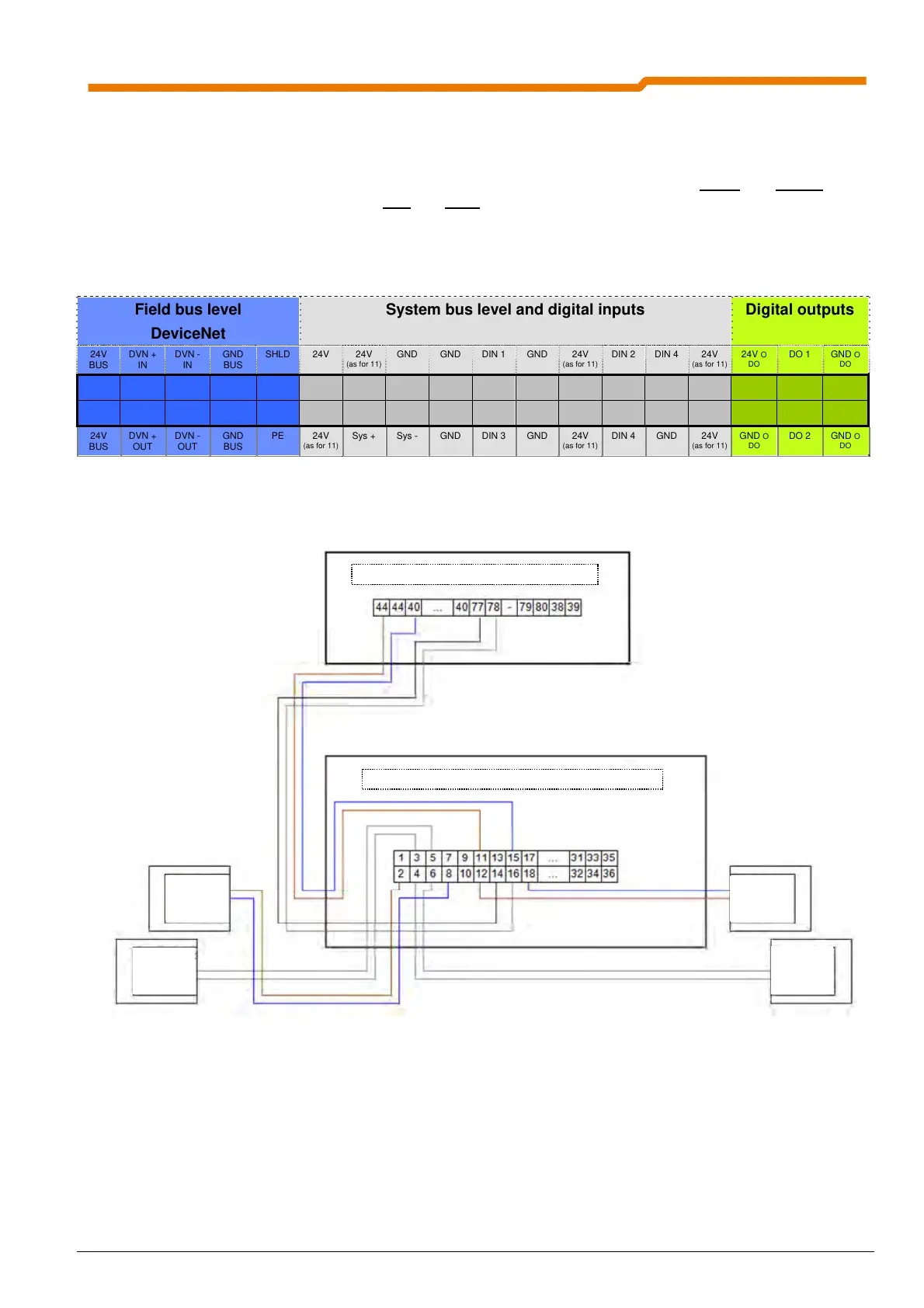
2.2.2.2 Control connections for SK TU4-DEV(-…)
The double spring-loaded terminal bar of the technology unit is colour coded, and therefore indicates the three
different potential levels.
A separate voltage source can be used to supply the DOs. However, by bridging the 24V o
and GND o to one
of the terminals of the system bus level 24V
and GND it is possible to implement the supply of the DOs.
Connection of up to 4 sensors and 2 actuators is made via the terminal bar. Alternatively, the
SK TU4-DEV
-M12 module enables the connection of these I/Os via the M12 round plug connector (5 pin
socket, A-coded) mounted on the front.
Field bus level
DeviceNet
System bus level and digital inputs Digital outputs
24V
BUS
DVN +
IN
DVN -
IN
GND
BUS
SHLD 24V 24V
(as for 11)
GND GND DIN 1 GND 24V
(as for 11)
DIN 2 DIN 4 24V
(as for 11)
24V O
DO
DO 1 GND O
DO
1 3 5 7 9 11 13 15 17 19 21 23 25 27 29 31 33 35
2 4 6 8 10 12 14 16 18 20 22 24 26 28 30 32 34 36
24V
BUS
DVN +
OUT
DVN -
OUT
GND
BUS
PE 24V
(as for 11)
Sys + Sys - GND DIN 3 GND 24V
(as for 11)
DIN 4 GND 24V
(as for 11)
GND O
DO
DO 2 GND O
DO
Connection example: SK TU4-DEV to SK 200E
SK205E… - connection unit (SK TI4...)
SK TU4-CAO… - connection unit (SK TI4-TU-BUS)
oltage
source
24V DC
ev
ce
e
participant
X-1
oltage
source
24V DC
ev
ce
et
participant
X+1

 Loading...

