EasyManua.ls Logo

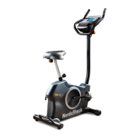
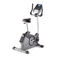
NordicTrack GX 2.5 NTEX23012.0 User Manual

NordicTrack GX 2.5 NTEX23012.0
28 pages
To Next Page IconTo Next Page
Page #1 background imageLoading...
Page #1 background image
www.nordictrack.com
Model No. NTEX23012.0
Serial No.
Write the serial number in the space
above for reference.
Serial Number Decal
(under frame)
QUESTIONS?
if you have questions, or if parts
are damaged or missing, DO NOT
CONTACT THE STORE; please
contact Customer Care.
iMPORTANT: Please register this
product (see the limited warranty
on the back cover of this manual)
before contacting Customer Care.
CALL TOLL-FREE:
1-800-TO-BE-FIT
(1-800-862-3348)
Mon.=Fri. 6 a.m.=6 p.m. MT
Sat. 8 a.m.-4 p.m. MT
ON THE WEB:
www.nordictrackservice.com
;ER'S A UAL
Question and Answer IconNeed help?

Do you have a question about the NordicTrack GX 2.5 NTEX23012.0 and is the answer not in the manual?

NordicTrack GX 2.5 NTEX23012.0 Specifications

General IconGeneral
Resistance TypeMagnetic
Resistance Levels16
DisplayYes
Display TypeLCD
Weight Capacity250 lbs
Display FeaturesTime, Speed, Distance, Calories
Warranty90 Days Parts
PedalsAdjustable Straps

Summary

IMPORTANT PRECAUTIONS

General Exercise Safety Precautions

Read all safety precautions and consult a physician before starting any exercise program.

ASSEMBLY

Attach Rear Stabilizer

Secure the rear stabilizer to the frame using M10 screws after placing protective material.

Attach Front Stabilizer

Secure the front stabilizer to the frame using M10 screws after placing protective material.

Adjust Seat Post Height

Loosen seat post knob, insert post, adjust height, then tighten knob securely.

Attach Seat to Seat Carriage

Connect the seat to the seat carriage using M8 screws and split washers.

Secure Seat Carriage to Seat Post

Mount the seat carriage onto the seat post and secure with the seat knob.

Install Handlebar and Pulse Wire

Route the pulse wire through the upright and attach the handlebar with M6 screws.

Connect Console Wires

Connect console wiring to extension and pulse wires, then attach the console.

Attach Pivot Cover

Slide and secure the pivot cover over the upright assembly using M4 screws.

Install Front Shield Cover

Slide the front shield cover onto the upright and secure it to the frame.

Install Pedals and Straps

Thread pedals into crank arms and adjust pedal strap positions for secure fit.

Connect Power Adapter

Plug the power adapter into the designated receptacle on the exercise bike frame.

HOW TO USE THE EXERCISE BIKE

FEATURES OF THE CONSOLE

HOW TO USE THE MANUAL MODE

Starting and Selecting Manual Mode

Turn on the console by pedaling or pressing a button, then select manual mode.

HOW TO USE AN ONBOARD WORKOUT

HOW TO USE A SET-A-GOAL WORKOUT

HOW TO USE AN IFIT LIVE WORKOUT

HOW TO CHANGE CONSOLE SETTINGS

MAINTENANCE AND TROUBLESHOOTING

HOW TO ADJUST THE DRIVE BELT

Drive Belt Tension Adjustment

Adjust drive belt tension by tightening the M10 x 50mm Hex Screw (48).
EXERCISE GUIDELINES

LIMITED WARRANTY

Related product manuals