DUCTEDRETURNAIR
M3furnaceswithmodelnumbersendinginAW
or BWarefactoryconfiguredfor thereturnair
to flowthroughthe frontIouvereddoor.The
returnairmayalsobeattachedtoeithersideor
the top of the furnacecabinetusinga field
installedkit.RefertoTable10fortheNORDYNE
ductedreturnkitP/Nnumber.Thelocationand
sizeofthesideandtopreturnairconnections
areshowninFigure1.Thefiltersizefortheside
returnairis20"x20"x1".Fortopreturnthefilter
sizeis24"x 16"x 1".
M3 furnaceswith modelnumbersendingin
BWTarefactoryconfiguredforthereturnairto
enterthetopof thefurnace.
AIR DISTRIBUTION SYSTEMS
For proper air distribution, the supply duct
system must be designed so that the static
pressure measured external to the furnace
does not exceed the listed static pressure
rating shown on the furnace rating plate.
Three typical distribution systems are illus-
trated in Figure 2. Location, size, and number
of registers should be selected on the basis of
best air distribution and floor plan of the home.
DUCT CONNECTOR SELECTION
PLATINUM SERIES
a. For Platinum ready construction use
the 14" round plenum, p/n: 903896.
NON=PLATINUM SERIES
a.
b.
Determine depth of floor cavity from
surface of floor to top of supply air duct
(See Figure 3).
Select appropriate model from Table 5
which matches X-dimension of the floor
cavity. To maximize air delivery, re-
move reducer "C" (see Figure 5) to
obtain the largest open area that will fit
the duct/floor construction.
MOUNTING
PLATE
FLOOR
OPENING
REAR WALL
SUPPLY AIR DUCT
FUEL
LINE
HOLES
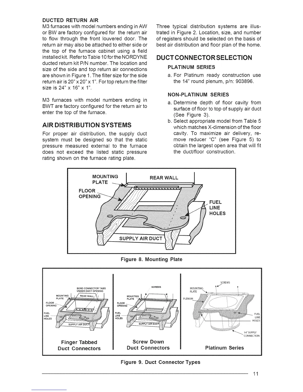
Figure 8. Mounting Plate
BEND CONNECTOR TABS
UNDER DUCT OPENING
Finger Tabbed
Duct Connectors
Screw Down
Duct Connectors
MOUNTING
PLATE
SCREWS
CONNECTION
Platinum Series
Figure 9. Duct Connector Types
11



 To Next Page