BLUE BLUE
SUPPLY AIR FLAME ROLL-OUT
_s)LIMIT SWITCH SW_TC H
VENT
SAFETY
SWITCH
WHITE (NEUTRAL) .....
BLACK 120V .....
GROUND ....
ROOM THERMOSTAT
I I
I I
I I
IITIONER I m I
I= r
I I
I
FLAMESENSOR
RED
Legend
Field Wiring
= =
YELLOW
BROWN
IGNITOR
Factory Wiring:
Low Voltage
High VoJtage
'I_ GREEN
TRANSFORMER E]
WHITE W/BLK STRIPES WHIT
,vl[....
BLK W/WHITE STRIPES BLACK
_]mCWl_A&$
|l-"
==_._L====
BLACK
BLACK
BLOWER DECK SWtTCH
2 _
3
4
5
i
i, ,4":_r_-
ORANGE
BLUE
BLACK
MOTOR
PLUG
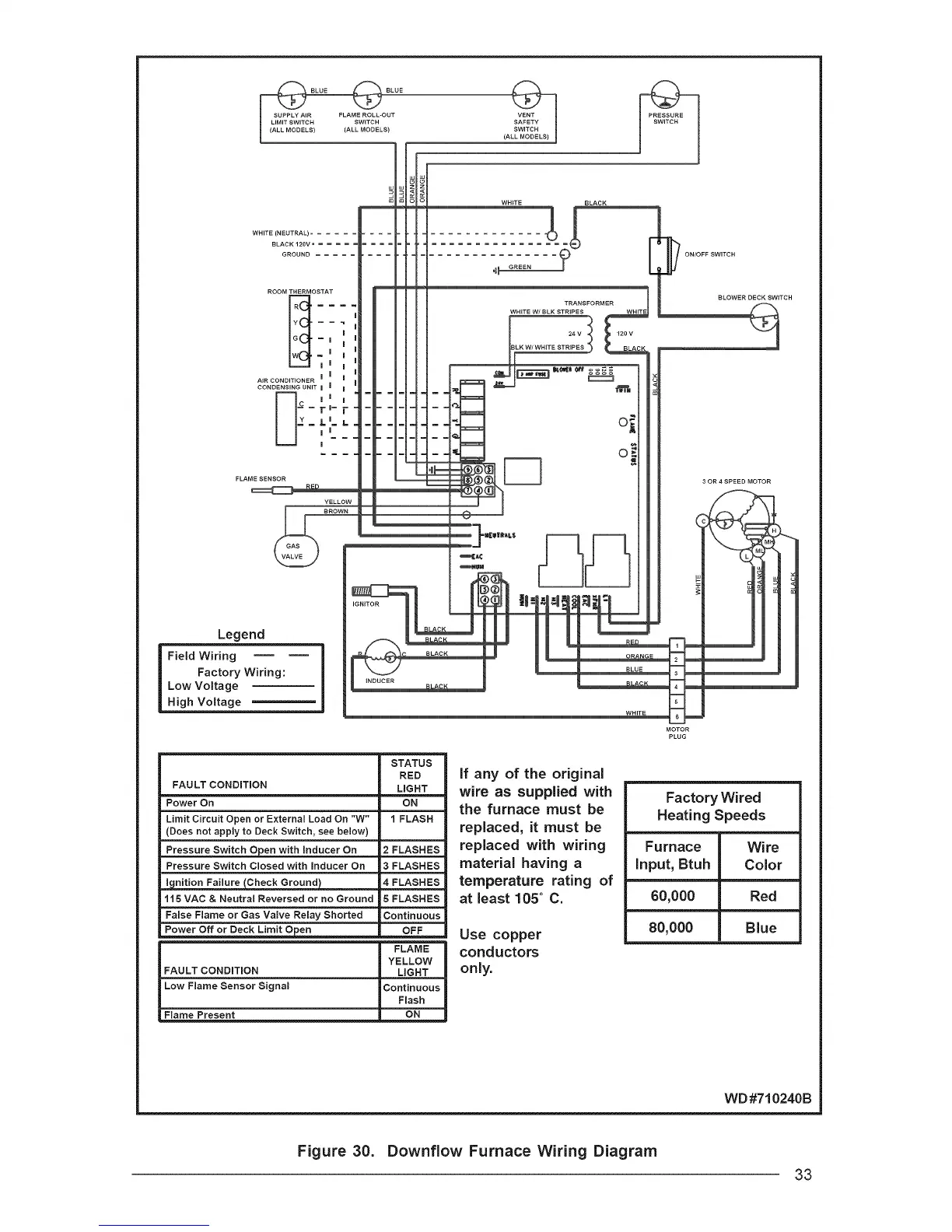
FAULT CONDITION
Power On
Limit Circuit Open or External Load On "W"
(Does not apply to Deck Switch, see below)
Pressure Switch Open with inducer On
Pressure Switch Closed with inducer On
STATUS
RED
LIGHT
ON
1 FLASH
2FLASHES
3FLASHES
ignition Failure (Check Ground)
115 VAC & Neutral Reversed or no Ground
False Flame or Gas Valve Relay Shorted
Power Off or Deck Limit Open
FAULT CONDiTiON
Low Flame Sensor Signal
Flame Present
4 FLASHES
5 FLASHES
Continuous
OFF
FLAME
YELLOW
LIGHT
Continuous
Flash
ON
if any of the original
wire as supplied with
the furnace must be
replaced, it must be
replaced with wiring
material having a
temperature rating of
at least 105 ° C.
Use copper
conductors
only.
Factory Wired
Heating Speeds
Furnace Wire
input, Btuh Color
60,000 Red
80,000 Blue
WD#710240B
Figure 30. Downflow Furnace Wiring Diagram
33