DUCT INSTALLATION
Required floor, ceiling, and roof cut-out open-
ings must be carefully located to avoid mis-
alignment of the furnace (see Figures 6 & 7).
Installation procedures are suggested for typi-
cal furnace installations and need not be fol-
lowed in the exact listed sequence.
CUT OUT FLOOR OPENING & FUEL LINE
HOLE
a. Determine center of closet or alcove (Fig-
ures 7 & 8).
b. Locate center of the floor opening, mea-
sured 10" from the rear wall, and mark cut-
out measuring approximately 14-1/2" by 14-
1/2" (+ 1") for model duct connector used
(refer to Figures 4 & 5).
c. Locate center of gas line hole, measured 23-
1/4" from the rear wall and 6-5/8" to the left of
center of the floor cut=out (See Figure 6) or
5-1/4" to the left of center of the floor cut-out,
or for entry through right-side of furnace
measured 9" to the right of center of the floor
cut-out.
d. Cut out floor opening and one gas line hole.
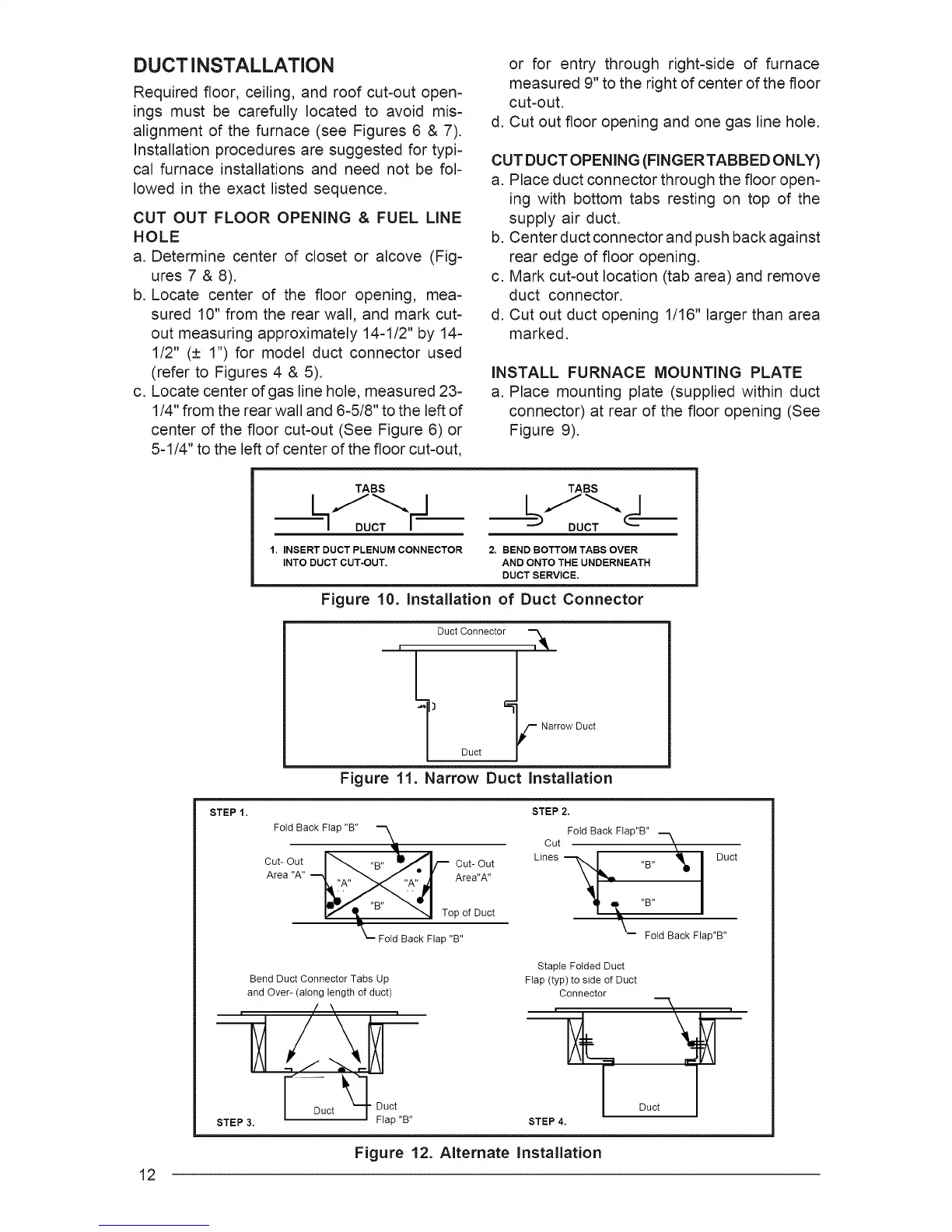
CUT DUCT OPENING (FINGERTABBED ONLY)
a. Place duct connector through the floor open-
ing with bottom tabs resting on top of the
supply air duct.
b. Center duct connector and push back against
rear edge of floor opening.
c. Mark cut-out location (tab area) and remove
duct connector.
d. Cut out duct opening 1/16" larger than area
marked.
INSTALL FURNACE MOUNTING PLATE
a. Place mounting plate (supplied within duct
connector) at rear of the floor opening (See
Figure 9).
12
TABS TABS
111--..... I/--.....
1. INSERT DUCT PLENUM CONNECTOR
INTO DUCT CUT-OUT.
2. BEND BOTTOM TABS OVER
AND ONTO THE UNDERNEATH
DUCT SERVICE.
Figure 10. Installation of Duct Connector
Duct Connector t-_
t) Duct _ Narrow Duct
Figure 11. Narrow Duct Installation
STEP 1.
Fold Back Flap "B"
Cut- Out
Area "A"
Cut- Out
Area"A"
Top of Duct
Fold Back Flap "B"
STEP2.
Fold Back Flap"B"
Cut "--_
Lines "__lt "B"'B" _ Duct
Fold Back Flap"B"
Bend Duct Connector Tabs Up
and Over- (along length of duct)
/ \
Staple Folded Duct
Flap (typ) to side of Duct
Connector
-k
Duct7
STEP 4.
Figure 12. Alternate Installation