/!X ATTENTION:
Lots des operations d'entretien des
commandes, _tiqueter tous les flies
avant des les d_connecter. Toute erreur
de c,iblage peut _tre une source de
danger et de panne.
S'assurer du bon fonctionnement de
I'appareil apr_s tout entretien.
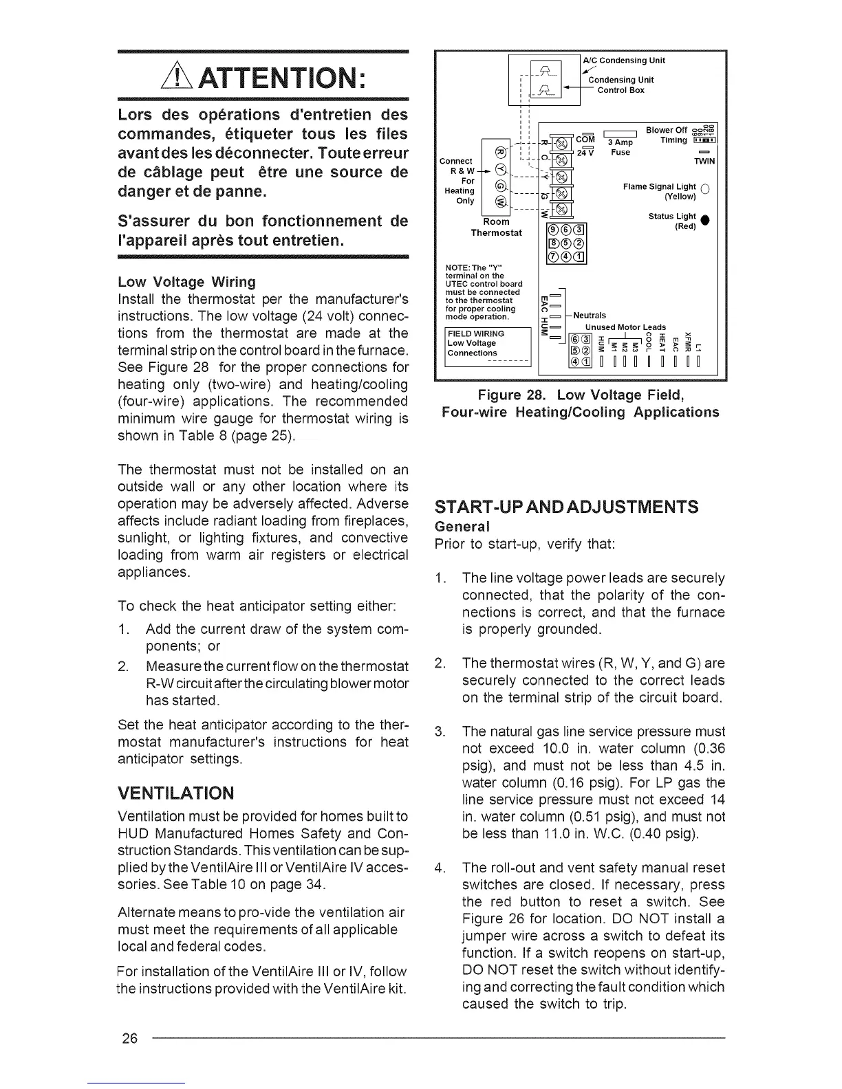
Low Voltage Wiring
Install the thermostat per the manufacturer's
instructions. The low voltage (24 volt) connec=
tions from the thermostat are made at the
terminal strip on the control board in the furnace.
See Figure 28 for the proper connections for
heating only (two=wire) and heating/cooling
(four=wire) applications. The recommended
minimum wire gauge for thermostat wiring is
shown in Table 8 (page 25).
_ Condensing Unit
[-I _ I_ I C°ndensingunit
,, [m__ F_[_j control Box
Connect m _;-m '-I-
R & W _- _LN. .... i
ForI _1
Heating I _m- .....
Only _ .....
Room
Thermostat
NOTE: The "Y"
terminal on the
UTEC control board
must be connected
to the thermostat
for proper cooling
mode operation.
FIELD WIRING
Low Voltage
Connections
oo
oo(--1_
;0 CO=M [_ Blower Off
3 Amp Timing
O_ 24==V Fuse
-i-_1
TWIN
:_t®l
_ Flame Signal Light O(Yellow)
Status Light _
(Red)
-i- Neutrals
C = I Unused Motor Leads
I_,_1 c'_ _ _'o > _ _ _-
I III I II II
Figure 28. Low Voltage Field,
Four=wire Heating/Cooling Applications
The thermostat must not be installed on an
outside wall or any other location where its
operation may be adversely affected. Adverse
affects include radiant loading from fireplaces,
sunlight, or lighting fixtures, and convective
loading from warm air registers or electrical
appliances.
To check the heat anticipator setting either:
1. Add the current draw of the system com-
ponents; or
2. Measure the current flow on the thermostat
R-W circuit after the circulating blower motor
has started.
Set the heat anticipator according to the ther-
mostat manufacturer's instructions for heat
anticipator settings.
VENTILATION
Ventilation must be provided for homes built to
HUD Manufactured Homes Safety and Con-
struction Standards. This ventilation can be sup-
plied by the VentilAire III or VentilAire IV acces-
sories. See Table 10 on page 34.
Alternate means to pro-vide the ventilation air
must meet the requirements of all applicable
local and federal codes.
For installation of the VentilAire Ill or IV, follow
the instructions provided with the VentilAire kit.
START=U PAND ADJUSTMENTS
General
Prior to start-up, verify that:
.
The line voltage power leads are securely
connected, that the polarity of the con-
nections is correct, and that the furnace
is properly grounded.
2. The thermostat wires (R, W, Y, and G) are
securely connected to the correct leads
on the terminal strip of the circuit board.
.
The natural gas line service pressure must
not exceed 10.0 in. water column (0.36
psig), and must not be less than 4.5 in.
water column (0.16 psig). For LP gas the
line service pressure must not exceed 14
in. water column (0.51 psig), and must not
be less than 11.0 in. W.C. (0.40 psig).
.
The roll-out and vent safety manual reset
switches are closed. If necessary, press
the red button to reset a switch. See
Figure 26 for location. DO NOT install a
jumper wire across a switch to defeat its
function. If a switch reopens on start=up,
DO NOT reset the switch without identify-
ing and correcting the fault condition which
caused the switch to trip.
26