.._.__.__...__-_ Collector Box
Clamp _iiill I
Step 1 :
Step 2:
Burner Box
Step 3:
j _ Keep
Floor _ _-'Y"
AIt. Drain
AIt. Drain
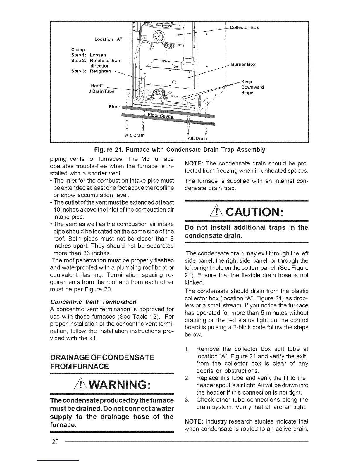
Figure 21. Furnace with Condensate Drain Trap Assembly
piping vents for furnaces. The M3 furnace
operates trouble=free when the furnace is in-
stalled with a shorter vent.
• The inlet for the combustion intake pipe must
be extended at least one foot above the roofline
or snow accumulation level.
• The outlet of the vent must be extended at least
10 inches above the inlet of the combustion air
intake pipe.
• The vent as well as the combustion air intake
pipe should be located on the same side of the
roof. Both pipes must not be closer than 5
inches apart. They should not be separated
more than 36 inches.
The roof penetration must be properly flashed
and waterproofed with a plumbing roof boot or
equivalent flashing. Termination spacing re-
quirements from the roof and from each other
must be per Figure 20.
Concentric Vent Termination
A concentric vent termination is approved for
use with these furnaces (See Table 12). For
proper installation of the concentric vent termi-
nation, follow the installation instructions pro-
vided with the kit.
NOTE: The condensate drain should be pro-
tected from freezing when in unheated spaces.
The furnace is supplied with an internal con-
densate drain trap.
CAUTION:
Do not install additional traps in the
condensate drain,
The condensate drain may exit through the left
side panel, the right side panel, or through the
left or right hole on the bottom panel. (See Figure
21). Ensure that the flexible drain hose is not
kinked.
The condensate should drain from the plastic
collector box (location "A", Figure 21) as drop=
lets or a small stream. If you notice the furnace
has operated for more than 5 minutes without
draining or the red status light on the control
board is pulsing a 2-blink code follow the steps
below.
DRAINAGE OF CONDENSATE
FROM FURNACE
/t WARNING:
The condensate produced by the furnace
must be drained, Do not connect awater
supply to the drainage hose of the
furnace,
1. Remove the collector box soft tube at
location "A", Figure 21 and verify the exit
from the collector box is clear of any
debris or obstructions.
2. Replace this tube and verify the fit to the
header spout is air tight. Air will be drawn into
the header if this connection is not tight.
3. Check other tube connections along the
drain system. Verify that all are air tight.
NOTE: Industry research studies indicate that
when condensate is routed to an active drain,
2O