VentConfigurationto
Provide12"Minimum
heightabove _
Snow Level. 12" Min.
19" Max.
Support
Outside _ " __
Wail ' '_
1,,2"
:__ insulation ol
__ _ Equivalent
red),
12"Above
Normally
Expected
Snow
Level
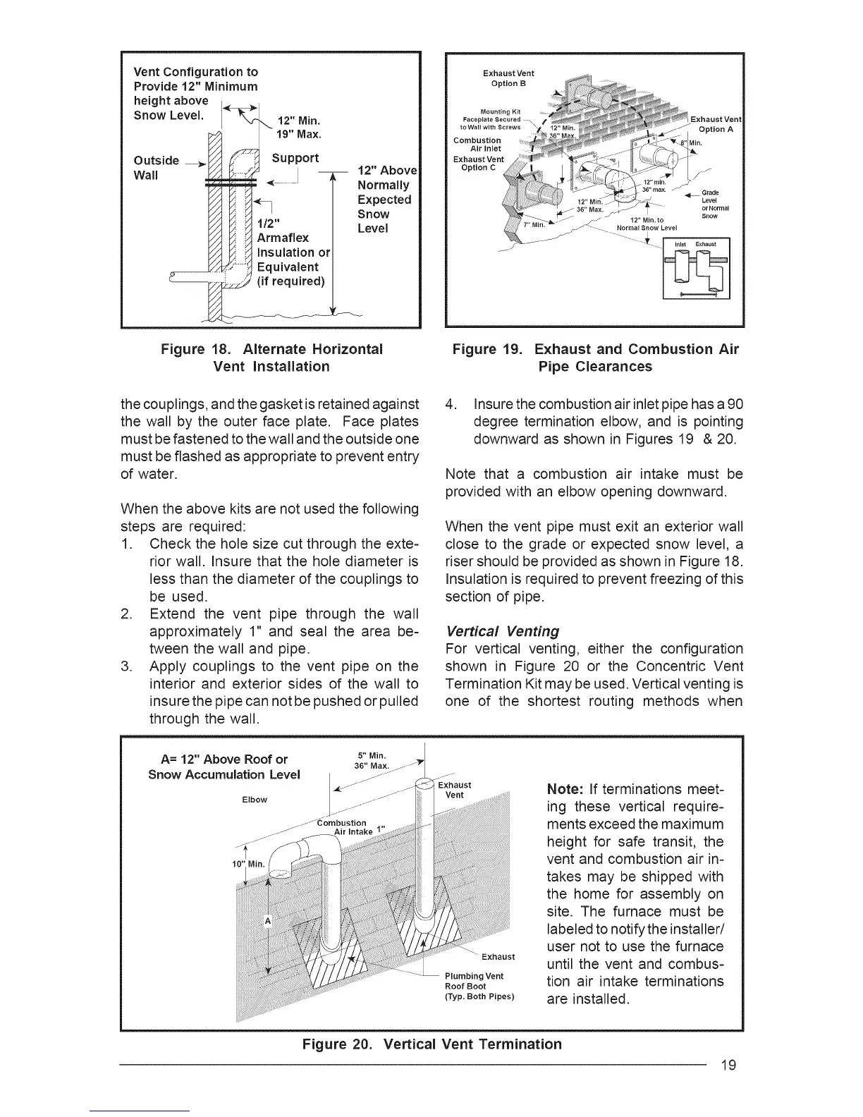
Figure 18. Alternate Horizontal
Vent Installation
Exhaust Vent
Option B
Mounting
FacepIate Secured
Combustion
Air Inlet
Exhaust Vent
Option C
Exhaust Vent
ion A
Grade
Level
jJ 12" Min, to
_fJ Normal Snow Level
,o,o,
Figure 19. Exhaust and Combustion Air
Pipe Clearances
the couplings, and the gasket is retained against
the wall by the outer face plate. Face plates
must be fastened to the wall and the outside one
must be flashed as appropriate to prevent entry
of water.
When the above kits are not used the following
steps are required:
1. Check the hole size cut through the exte-
rior wall. Insure that the hole diameter is
less than the diameter of the couplings to
be used.
2. Extend the vent pipe through the wall
approximately 1" and seal the area be-
tween the wall and pipe.
3. Apply couplings to the vent pipe on the
interior and exterior sides of the wall to
insure the pipe can not be pushed or pulled
through the wall.
4. Insure the combustion air inlet pipe has a 90
degree termination elbow, and is pointing
downward as shown in Figures 19 & 20.
Note that a combustion air intake must be
provided with an elbow opening downward.
When the vent pipe must exit an exterior wall
close to the grade or expected snow level, a
riser should be provided as shown in Figure 18.
Insulation is required to prevent freezing of this
section of pipe.
Vertical Venting
For vertical venting, either the configuration
shown in Figure 20 or the Concentric Vent
Termination Kit may be used. Vertical venting is
one of the shortest routing methods when
A= 12" Above Roof or 5-Min.
36" Max.
Snow Accumulation Level
Elbow
.... Exhaust
Plumbing Vent
Roof Boot
(Typ. Both Pipes)
Note: If terminations meet=
ing these vertical require-
ments exceed the maximum
height for safe transit, the
vent and combustion air in-
takes may be shipped with
the home for assembly on
site. The furnace must be
labeled to notify the installer/
user not to use the furnace
until the vent and combus-
tion air intake terminations
are installed.
Figure 20. Vertical Vent Termination
19