any of the originalwireas suppliedwiththe
furnacemustbereplaced,it mustbereplaced
withwirehavinga minimumtemperaturerating
of 105°C.Refertothefurnacenameplateand
Table8 for electricalrequirements.
Line Voltage Wiring
Thelinevoltage(115volt)tothefurnacemust
be suppliedfrom a dedicatedbranchcircuit
containingthe correctfuseor circuitbreaker
for thefurnace.SeeTable8. An electrical
switchshouldbereadilyaccessiblefromand
withinsightof the furnace. Seethe Wiring
Diagramlabelinthefurnacefor moredetails.
The furnacecabinetmusthave an uninter-
rupted,unbrokengroundto minimizeinjury
shouldanelectricalfaultconditionoccur.The
controlsusedinthisfurnacerequireanearth
groundtooperateproperly.Acceptablemeth-
odsforgroundingareelectricalwireorconduit
approvedforelectricalgroundservice.Donot
usegaspipingasanelectricalground.
NOTE:Properline voltagepolaritymust be
maintainedin orderforthe controlsystemto
operatecorrectly.Verifythattheincomingneu-
trallineis connectedtothewhitewireandthe
incoming"hot"line is connectedto the black
wireinthefurnacejunctionbox.Thefurnacewill
not operateunlesspolarityandgroundare
properlyconnected.SeeFigure26.
/!X CAUTION:
Label all wires prior to disconnection
when servicing controls. Wiring errors
can cause improper and dangerous
operation,
Verify proper operation after servicing,
::ul_l _OM _ BIowerOff
Timing
24 V
TWINFlame Signal
Light (Yellow) O
Status
Light (Red) O
Common
Leads Neutrals
> Z/] _ Unused Motor
Connect Io _ Leads
Neutral _ _ _ _ 3: © x
Leadof _ Ir_nq _ _ _ _ _ o° _- _
AirCI ..... IIIIII II
..... I 11Elect
and/or Humidifier
H.... tl If
/ I LElectronic Air Tap
Humidifier Tap | (.5A@ 120 VAC)
(.5A@ 120 VAC) _ I These motor speed taps are
L not used for two-stage models
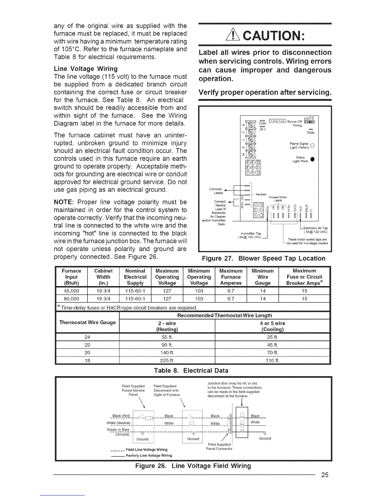
Figure 27. Blower Speed Tap Location
Furnace Cabinet Nominal Maximum Minimum
Input Width Electrical Operating Operating
(Btuh) (in.) Supply Voltage Voltage
45,000 19 3/4 115-60-1 127 103
80,000 19 3/4 115-60-1 127 103
Time-delay fuses or HACR-type circuit breakers are required.
Thermostat Wire Gauge
24
22
2O
18
Maximum Minimum
Furnace Wire
Amperes Gauge
9.7 14
9.7 14
Maximum
Fuse or Circuit
Breaker Amps _
15
15
Recommended Thermostat
2 - wire
(Heating)
55 ft.
90 ft.
140 ft.
225 ft.
Wire Length
4 or 5 wire
(Cooling)
25 ft.
45 ft.
70 ft.
110 ft.
Table 8. Electrical Data
Field Supplied Field Supplied
Fused Service Disconnect w/in
Panel Sight of Furnace
\ \
Wh e (Neu ra) | White /, "_
Gr;:nor-=ar:...."1....I.......... L-_L-_.-_L-:
_r_nd_F--_---7 ....._---
[ Ground
...... Field Line Voltage Wiring
__ Factory Line Voltage Wiring
Junction Box (may be int. or ext.
to the furnace). These connections
can be made in the field supplied
disconnect at the furnace.
White
Panel Connector
Ground
Figure 26. Line Voltage Field Wiring
25
 Loading...