Do you have a question about the Nordyne M3RL 080A BWT and is the answer not in the manual?
Steps to take if you detect a gas leak, emphasizing immediate evacuation and professional contact.
Mandates installation and service by qualified professionals for safety and performance.
French safety warnings regarding fire, explosion, and gas leak procedures.
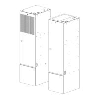
Provides physical dimensions of the furnace unit for installation planning.
Lists the weight of different furnace models for handling and installation.
Details furnace input, output, temp rise, motor specs, and airflow at various static pressures.
Warning against using appliances submerged in water and requiring immediate inspection.
Advises installers to follow all instructions for safety, performance, and warranty.
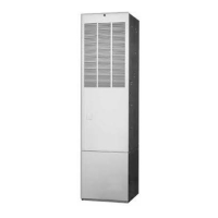
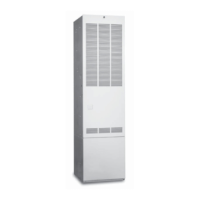
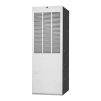
Describes the M3 series gas furnaces as direct vent, sealed combustion, Category IV appliances.
Information about NORDYNE's history and commitment to comfort in manufactured housing.
Outlines homeowner responsibilities for proper setup, fuel conversion, and adjustments.
Warns against altering or repairing furnace components due to safety risks.
Specific requirements for side wall horizontal venting installation in Massachusetts.
Requirements for installing carbon monoxide detectors with side wall vented equipment.
Specifies required signage for horizontal vent terminals indicating gas vent location.
Requirements for inspection by local gas inspectors, including detectors and signage.
Manufacturer's requirements for special venting systems not included with the equipment.
Warning about preventing combustion products from entering the return air.
General requirements for air supply and ductwork installation.
Details how M3 furnaces handle return air, including factory configurations and kits.
Guidance on designing supply duct systems for proper air distribution.
Instructions for selecting and installing duct connectors for various furnace configurations.
Specific steps for determining and making floor cut-outs for the furnace and gas line.
Instructions for cutting duct openings when using finger-tabbed duct connectors.
Steps for installing the furnace mounting plate at the rear of the floor opening.
Specific installation steps for platinum series round duct connectors.
Instructions for installing screw-down type duct connectors.
Procedures for installing finger-tabbed duct connectors, including alternate methods.
Warning to prevent snow or debris from blocking air intake or vent pipes.
Warning that combustion air piping must not be blocked or restricted.
Warning that alternative installation methods must comply with codes for air supply.
Caution against allowing debris to fall into the furnace, which can cause unsafe operation.
Lists maximum allowable direct vent, dual pipe lengths for different applications and pipe sizes.
Illustrates minimum required clearances for vent termination points from various building features.
Diagram showing an alternate method for horizontal vent installation near snow level.
Diagrams showing clearances for exhaust and combustion air pipe terminations.
Diagram illustrating vertical vent termination requirements and pipe setup.
Diagram showing the furnace condensate drain trap assembly and its components.
Caution against installing additional traps in the condensate drain line.
Warning against using open flames for gas leak detection.
Procedure for testing gas piping connections for leaks.
Information on derating furnace input for elevations above 4,000 feet.
Critical warning about qualified installation of conversion kits to prevent hazards.
Warning not to remove or deface the original rating plate.
Precaution to shut off gas supply before disconnecting electrical power for conversion.
Steps to safely turn off the fuel supply before performing conversion.
Detailed instructions for removing the burner assembly for conversion.
Steps for removing and replacing burner orifices during conversion.
Caution against re-drilling orifices; advises using new orifices for size changes.
Guidelines for installing pressure gauges for natural and LP gas lines.
Step-by-step procedure for lighting and adjusting the furnace operation.
Warning to turn off power before making electrical connections to prevent shock.
Information on manifold pressure settings for natural and LP gas.
Final steps for conversion, including affixing labels and running a complete cycle.
Provides electrical specifications like input, voltage, current, and wire gauge requirements.
Diagram illustrating line voltage field wiring connections to the furnace.
Table for converting gas meter time per revolution to gas flow rate.
Safety warning to turn off power before performing any maintenance.
Warning about hazards from leaks in vent pipes or heat exchangers.
Guidance on inspecting the combustion air and vent system for damage or blockages.
Instructions for changing or cleaning air filters monthly.
Warning against operating the furnace without an air filter.
Information on blower motor lubrication (pre-lubricated).
Checks for condensate drain lines to ensure they are free, open, and free of kinks.
Recommendation to clean the blower compartment monthly to remove dirt and lint.
Annual inspection and cleaning of heat exchanger, vent system, and burners.
General information on proper maintenance for optimal furnace performance.
Detailed description of operating sequences for heating, cooling, and fan modes.
Sequence of operations for the cooling mode of the furnace.
Sequence of operations for the fan-only mode.
Table showing gas pipe capacity based on diameter, length, and specific gravity.
Table listing approximate orifice sizes for natural and LP gas at different altitudes.
| Brand | Nordyne |
|---|---|
| Model | M3RL 080A BWT |
| Category | Furnace |
| Efficiency Rating | 80% AFUE |
| Fuel Type | Natural Gas |
| Blower Type | Multi-speed |
| Blower Motor Type | PSC |
| Vent Diameter | 4 inches |
| Heating Capacity | 80000 BTU |
| Thermostat Compatibility | Standard |