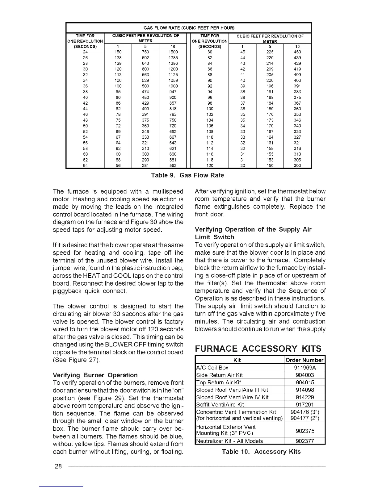
TIME FOR
ONE REVOLUTION
(SECONDS)
24
26
28
30
32
34
36
38
40
42
44
46
48
50
52
54
56
58
60
62
64
CUBIC FEET PER REVOLUTION OF
METER
1
150
138
129
120
113
106
100
95
90
86
82
78
75
72
69
67
64
62
60
58
56
5 10
750 1500
692 1385
643 1286
600 1200
563 1125
529 1059
500 1000
474 947
450 900
429 857
409 818
391 783
375 750
360 720
346 692
333 667
321 643
310 621
300 600
290 581
281 563
GAS FLOW RATE (CUBIC FEET PER HOUR)
TIME FOR
ONE REVOLUTION
(SECOoNDS)
82
84
86
88
9O
92
94
96
19080
102
104
106
108
110
112
114
116
118
120
CUBIC FEET PER REVOLUTION OF
METER
1
45
44
43
42
41
4O
39
38
38
37
36
35
35
34
33
33
32
32
31
31
30
5 10
225 450
220 439
214 429
209 419
205 409
200 400
196 391
191 383
188 375
184 367
180 360
176 353
173 346
170 340
167 333
164 327
161 321
158 316
155 310
153 305
150 300
Table 9. Gas Flow Rate
The furnace is equipped with a multispeed
motor. Heating and cooling speed selection is
made by moving the leads on the integrated
control board located in the furnace. The wiring
diagram on the furnace and Figure 30 show the
speed taps for adjusting motor speed.
If it is desired that the blower operate at the same
speed for heating and cooling, tape off the
terminal of the unused blower wire. Install the
jumper wire, found in the plastic instruction bag,
across the HEAT and COOL taps on the control
board. Reconnect the desired blower tap to the
piggyback quick connect.
The blower control is designed to start the
circulating air blower 30 seconds after the gas
valve is opened. The blower control is factory
wired to turn the blower motor off 120 seconds
after the gas valve is closed. This timing can be
changed using the BLOWER OFF timing switch
opposite the terminal block on the control board
(See Figure 27).
Verifying Burner Operation
To verify operation of the burners, remove front
door and ensure that the door switch is in the "on"
position (see Figure 29). Set the thermostat
above room temperature and observe the igni-
tion sequence. The flame can be observed
through the small clear window on the burner
box. The burner flame should carry over be=
tween all burners. The flames should be blue,
without yellow tips. Flames should extend from
each burner without lifting, curling, or floating.
After verifying ignition, set the thermostat below
room temperature and verify that the burner
flame extinguishes completely. Replace the
front door.
Verifying Operation of the Supply Air
Limit Switch
To verify operation of the supply air limit switch,
make sure that the blower door is in place and
that there is power to the furnace. Completely
block the return airflow to the furnace by install-
ing a close-off plate in place of or upstream of
the filter(s). Set the thermostat above room
temperature and verify that the Sequence of
Operation is as described in these instructions.
The supply air limit switch should function to
turn off the gas valve within approximately five
minutes. The circulating air and combustion
blowers should continue to run when the supply
FURNACE
Kit
A/C Coil Box
Side ReturnAir Kit
Top ReturnAir Kit
Sloped Roof VentilAire III Kit
Sloped Roof VentilAire IV Kit
Soffit VentilAire Kit
Concentric Vent Termination Kit
(for horizontal and vertical venting)
Horizontal Exterior Vent
Mounting Kit (3" PVC)
Neutralizer Kit - All Models
Table 10.
ACCESSORY KITS
Order Number
911969A
904003
904015
914098
914229
917201
904176 (3")
904177 (2")
902375
902377
Accessory Kits
28