MANUFACTURERREQUIREMENTS-
GASEQUIPMENTVENTINGSYSTEM
NOT PROVIDED.
When the manufacturer of a Product Approved
side wall horizontally vented gas fueled
equipment does not provide the parts for
venting the flue gases, but identifies" special
venting systems", the following requirements
shall be satisfied by the manufacturer:
1. The reference "special venting
system" instructions shall be
included with the appliance or
equipment instructions; and
2. The "special venting systems" shall
be Product Approved by the board,
and the instructions for that system
shall include a part list and detailed
installation instructions.
A copy of all installation instructions for all
Product Approved side wall horizontally vented
gas fueled equipment, all venting instructions,
all parts lists for venting instructions, and/or all
venting design instructions shall remain with
the appliance or equipment at the completion
of the installation.
A Single trunk duct
, D
_" Dual trunk duct
B w/crossover connector
I
Transition duct
C [p w/branches [']____[1_
7
II II II
Figure 2. Non-Platinum
Supply Duct System
LOCATION
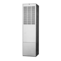
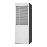
The furnace must be installed on a level sur-
face, and as close to the center of the air
distribution system as possible. See Figure 1
for overall dimensions to determine the required
clearances in hallways, doorways, stairs, etc.
to allow the furnace to be moved to the instal=
lation point. The furnace must be installed so
that all electrical components are protected
from water.
Minimum clearances to combustible materials
are listed in Table 4. Access for positioning and
servicing must be considered when locating the
unit.
This furnace is certified for use on wood floor=
ing. The furnace must be installed on a solid
surface and must be level front-to-back and
I I
Top View
of Duct
Connector
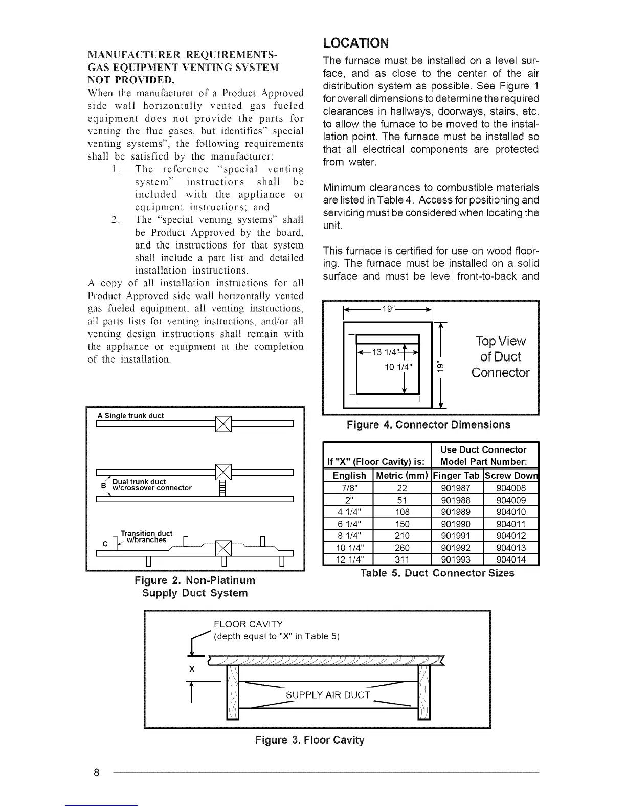
Figure 4. Connector Dimensions
Use Duct Connector
If "X" (Floor Cavity)is: Model Part Number:
English Metric (mm) Finger Tab Screw Dowr
7/8" 22 901987 904008
2" 51 901988 904009
4 1/4" 108 901989 904010
6 1/4" 150 901990 904011
8 1/4" 210 901991 904012
10 1/4" 260 901992 904013
12 1/4" 311 901993 904014
Table 5. Duct Connector Sizes
FLOOR CAVITY
(depth equal to "X" in Table 5)
Figure 3. Floor Cavity
8