Note: The size of the new orifices that will be
installed into the unit will depend upon the
type of conversion (sea level or high alti=
tude; natural gas or LP gas).
Honeywell II_1__
Valve
OTHER SIDE
PRESSURE
OF CAP
REGULATOR
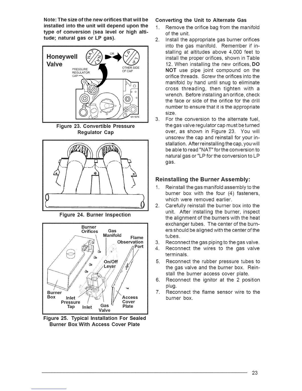
Figure 23. Convertible Pressure
Regulator Cap
Figure 24. Burner Inspection
Burner
Orifices
\
Gas
Manifold
Flame
Observation
Burner
Box Inlet Access
Pressure Cover
Tap Inlet Gas Plate
Valve
Figure 25. Typical Installation For Sealed
Burner Box With Access Cover Plate
Converting the Unit to Alternate Gas
1. Remove the orifice bag from the manifold
of the unit.
2. Install the appropriate gas burner orifices
into the gas manifold. Remember if in=
stalling at altitudes above 4,000 feet to
install the proper orifices, shown in Table
12. When installing the new orifices, DO
NOT use pipe joint compound on the
orifice threads. Screw the orifices into the
manifold by hand until snug to eliminate
cross threading, then tighten with a
wrench. Before installing an orifice, check
the face or side of the orifice for the drill
number to ensure that it is the appropriate
size.
3. For the conversion to the alternate fuel,
the gas valve regulator cap must be turned
over, as shown in Figure 23. You will
unscrew the cap and reinstall for your in-
stallation. After reinstalling the cap, you will
be able to read "NAT" for the conversion to
natural gas or "LP for the conversion to LP
gas.
Reinstalling the Burner Assembly:
1. Reinstall the gas manifold assembly to the
burner box with the four (4) fasteners,
which were removed earlier.
2. Carefully reinstall the burner box into the
unit. After installing the burner, inspect
the alignment of the burners with the heat
exchanger tubes. The center of the burn-
ers should be aligned with the center of the
tubes.
3. Reconnect the gas piping to the gas valve.
4. Reconnect the wires to the gas valve
terminals.
5. Reconnect the rubber pressure tubes to
the gas valve and the burner box. Rein-
stall the burner access cover plate.
6. Reconnect the ignitor at the 2 position
plug.
7. Reconnect the flame sensor wire to the
burner box.
23