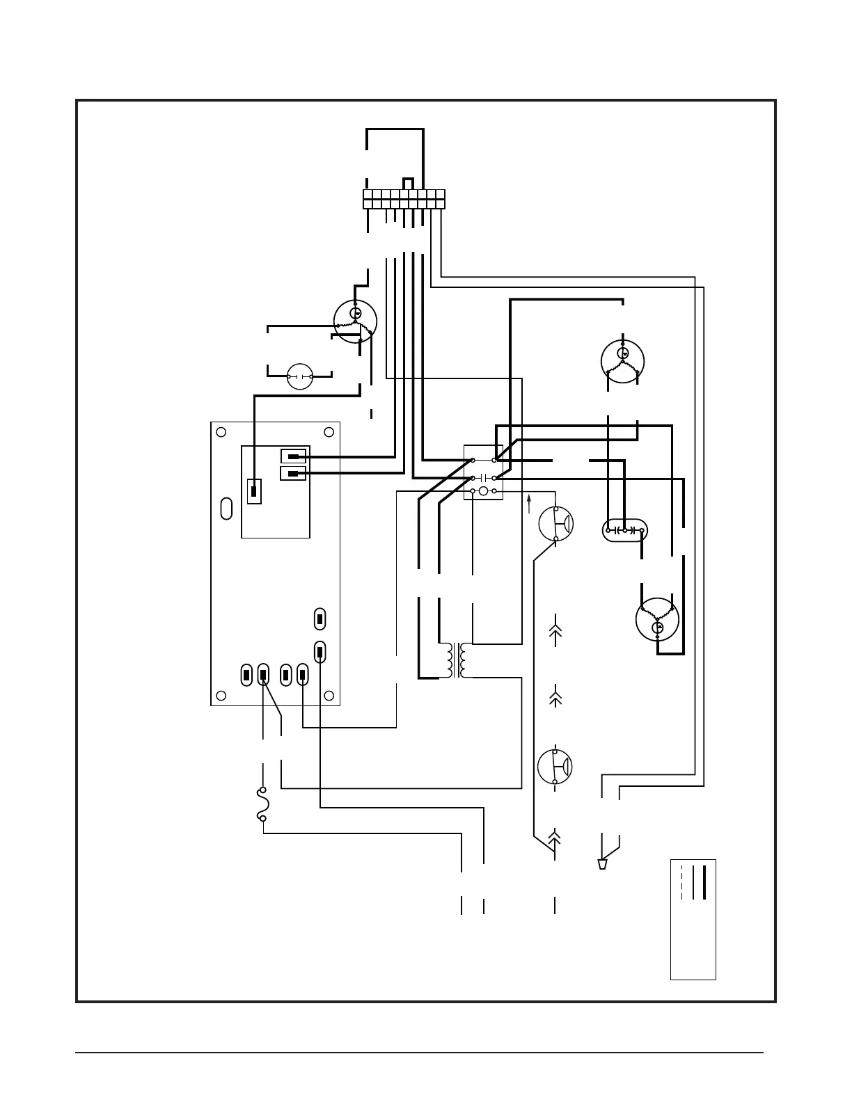
15
3 AMP
FUSE
COMPRESSOR
DUAL
CAPACITOR
S
R
C
L2 L1
T2 T1
COMPRESSOR
CONTACTOR
COM
240V
LOW PRESSURE SWITCH
(SELECT MODELS ONLY)
5
4
3
2
1
9
8
7
6
5
4
3
2
1
9
8
7
6
THERMOSTAT
THERMOSTAT
THERMOSTAT
F
H
C
TRANSFORMER
RED
BLACK
XFMR-R
XFMR-C
R
C
G
SPEEDUP
COM
N.O. N.C.
OUTDOOR
FAN MOTO R
S
R
C
BLUE
ORANGE
BLACK
H
L
C
CAPACITOR
BROWN
BROWN
BLACK
RELAY
CONTROL
BOARD
WHITE
BLOWER
MOTOR
RED
HIGH PRESSURE
SWITCH
YELLOW
YELLOW/BLACK
YELLOW/BLACK
YELLOW
YELLOW
1. Couper le courant avant de faire letretien.
2. Employez uniquement des conducteurs en cuivre.
3. Ne convient pas aux installations de plus de 150 V a la terre.
FIELD WIRING
LEGEND:
LOW VOLTAGE
HIGH VOLTAGE
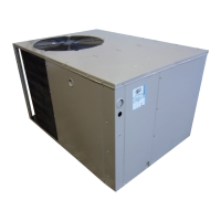
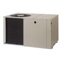
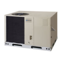
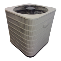
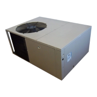
Packaged Air Conditioner - Single Phase
NOTES:
1. Disconnect all power before servicing.
2. For supply connections use copper conductors only.
3. Not suitable on systems that exceed 150 V to ground.
4. For replacement wires use conductors suitable for 105° C.
5. See installation instructions for blower motor airflow settings.
RED
RED
BLACK
WHITE
WHITE
BLUE
YELLOW
RED
GREEN
YELLOW
ORANGE
BROWN
BLACK
GREY
YELLOW
RED
WHITE
RED
RED
YELLOW
Figure 12. Wiring Diagram - P5RD with PSC Motor
WD # 7108260
 Loading...