8
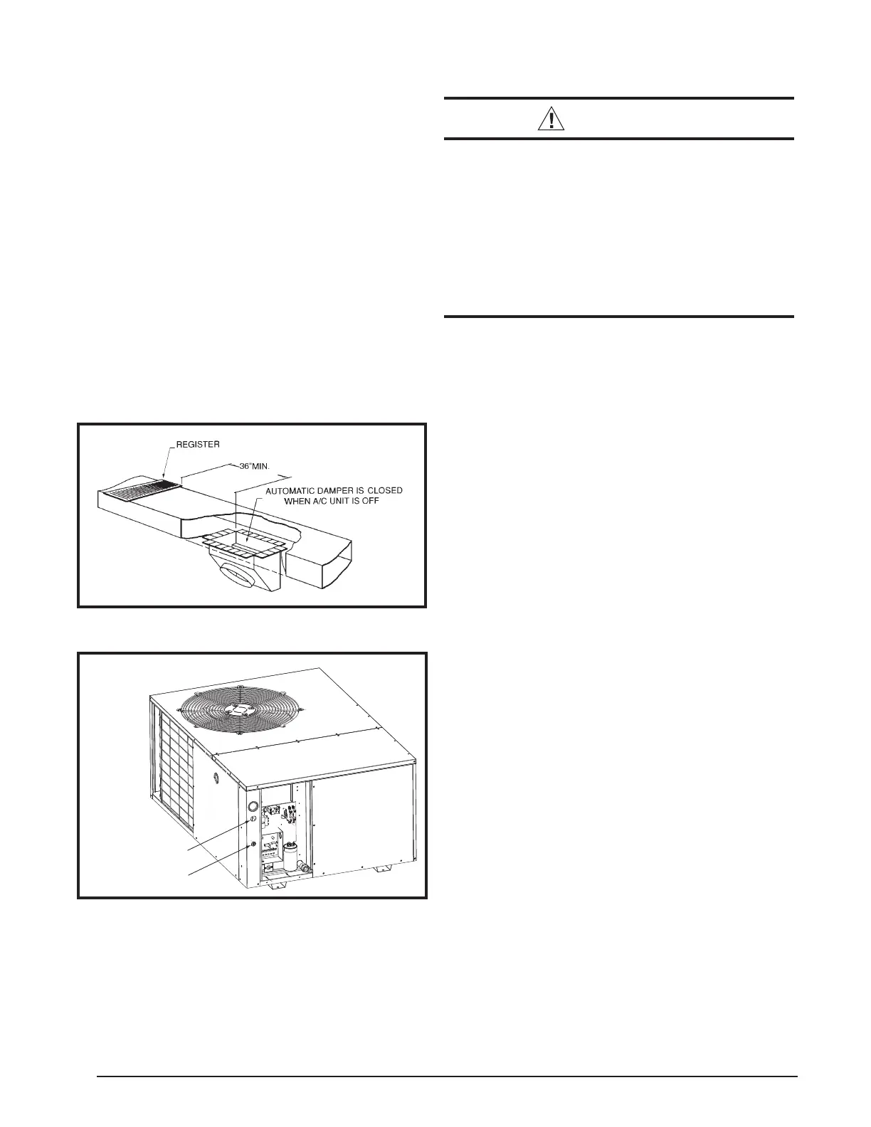
When locating the supply damper(s), carefully check
fl oor joists and frame members that could interfere with
the installation of the damper or fl exible duct. Ideally, the
damper (Figure 7) should be located in the bottom of the
main duct, forward of center of the home, at least three
feet from the nearest register. The round supply opening
in the slanted side of the damper should face the side of
the home where the air conditioner is located.
1. Locate the center of the heat duct by cutting a small
hole in the fi berboard below the duct at the desired
location.
2. Cut a hole approximately 3/4” larger than the damper
opening in the fi berboard.
3. Cut a 9-1/8” x 13-1/8” hole in the duct and bend over
all tabs fl at on the inside of the heat duct.
4. Insert the damper into the duct and bend over all tabs
fl at on the inside of the heat duct.
5. Seal the opening between the fi berboard and damper
or fl exible duct.
Figure 7. Supply Damper
ELECTRICAL CONNECTIONS
WARNING:
To avoid risk of electrical shock, personal
injury, or death, disconnect all electrical power
to the unit before performing any maintenance
or service. The unit may have more than one
electrical supply.
Label all wires prior to disconnection when
servicing the unit. Wiring errors can cause
improper and dangerous operation
• All electrical connections must be in compliance with
all applicable local codes and ordinances, and with
the current revision of the National Electric Code
(ANSI/NFPA 70).
• For Canadian installations the electrical connections
and grounding shall comply with the current Canadian
Electrical Code (CSA C22.1 and/or local codes).
Pre-Electrical Checklist
Verify that the voltage, frequency, and phase of the
supply source match the specifi cations on the unit
rating plate.
Verify that the service provided by the utility is suffi cient
to handle the additional load imposed by this equipment.
Refer to the unit wiring label for proper high and low
voltage wiring.
Verify factory wiring is in accordance with the unit wiring
diagram (Figures 11 or 12, pages 14 - 15). Inspect for
loose connections.
Line Voltage
• A wiring diagram is located on the inside cover of the
electrical box of the unit. The installer should become
familiar with the wiring diagram before making any
electrical connections to the unit.
• An electrical disconnect must be located within
sight of and readily accessible to the unit. This
switch shall be capable of electrically de-energizing
the unit.
• Line voltage to the unit should be supplied from a
dedicated branch circuit containing the correct fuse
or circuit breaker for the unit. Incoming fi eld wiring
and minimum size of electrical conductors and circuit
protection must be in compliance with information listed
on the unit data label. Any other wiring methods must
be acceptable to authority having jurisdiction.
• Provide power supply for the unit in accordance with the
unit wiring diagram, and the unit rating plate. Connect
the line-voltage leads to the terminals on the contactor
inside the control compartment. Extend leads through
power wiring hole (Figure 8). Connect L1 and L2 directly
to the contactor.
• The unit requires both power and control circuit electrical
connections. Refer to the wiring diagram / schematic
Figure 8. Power Entry
Low Voltage
Line Voltage
 Loading...