15
GND
INPUT
SUPERVISED INPUT
UNSUPERVISED INPUT
SHORTING OR CUTTING THE
INPUT WIRES
CAN
SIGNAL
A TROUBLE CONDITION
NORMALLY OPEN
GND
INPUT
NORMALLY CLOSED
1k OHM
1k OHM
SHORTING OR CUTTING THE
INPUT WIRES CANNOT SIGNAL
A TROUBLE CONDITION
PLACE THE RESISTOR NEAR THE
SWITCH TO SUPERVISE THE WIRE RUN
GND
INPUT
NORMALLY OPEN
GND
INPUT
NORMALLY CLOSED
DOOR
POSITION
CONTACT
GND
DSM
NOTE: IF DOOR SWITCH
CONTACT IS NORMALLY
CLOSED,
PROGRAM THE
INPUT TO NORMALLY CLOSED
DSM = DOOR SWITCH MONITOR INPUT
DOOR "A" OR "B"
DSM TERMINALS
INPUT DEFAULT STATE
DOOR SWITCH MONITOR
(DSM)
NORMALLY OPEN UNSUPERVISED
8 SECOND HELD OPEN TIME
REQUEST TO EXIT
(REX)
NORMALLY OPEN MOMENTARY
UNSUPERVISED
AUXILIARY INPUTS
NORMALLY OPEN
UNSUPERVISED
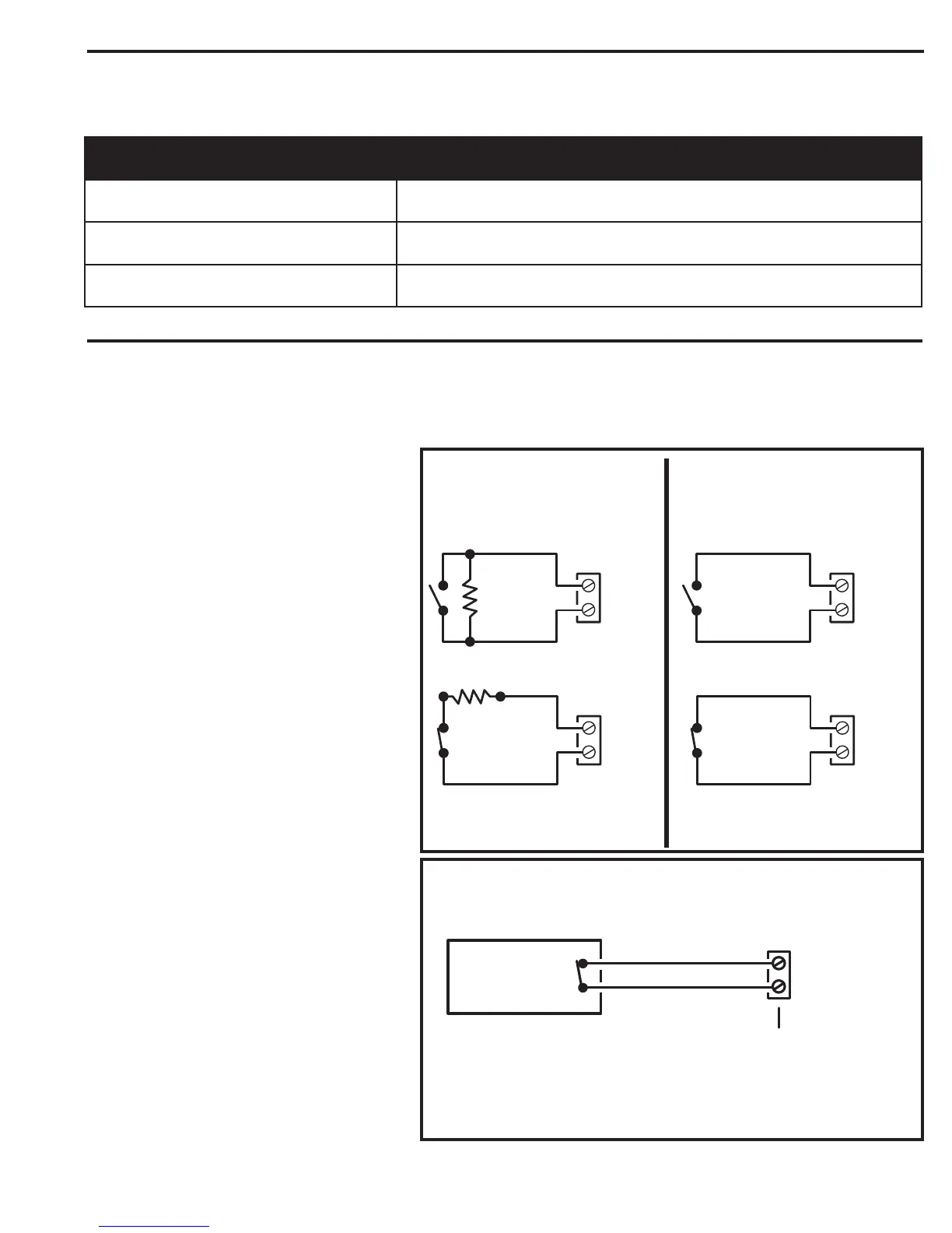
System Input Wiring
Systems have the three types of switch inputs used for monitoring door position (DSM), exit requests (REX), and auxiliary requests.
All inputs are assigned default features that can be congured as needed. The following table shows the default states for each of the inputs:
System Input Wiring
Systems have the three types of switch inputs used for monitoring door position (DSM), exit requests (REX), and auxiliary requests.
All inputs are assigned default features that can be congured as needed. The following table shows the default states for each of the inputs:
Input Options
All inputs may be congured for normally open
(factory default) or normally closed contacts with
supervision or non-supervision. Use 1k ohm resistors
for supervision. Refer to the gure for the acceptable
wiring congurations.
Door Switch Monitor (DSM) Inputs
The two DSM inputs for Door Lock Relays A & B can
connect to a door switch that monitors whether the
controlled door is open or closed. Doors are usually
monitored with a magnetic contact or mechanical
switch to detect forced entry or door ajar conditions.
1. To use the door switch monitor feature, install a
door switch on the door or pedestrian gate and
route two wires from the switch to the unit.
2. Connect the sensing device wires to the
associated relay sensing terminal DSM and GND
terminals.
 Loading...