6
1
2
3
4
5
6
7
11
10
9
8
45
37
40
42
44
43
41
38
39
12 13
24
26
28
30
31
29
27
25
22
23
14
15
16
17
18
19
20
21
32
33
34
35
36
46
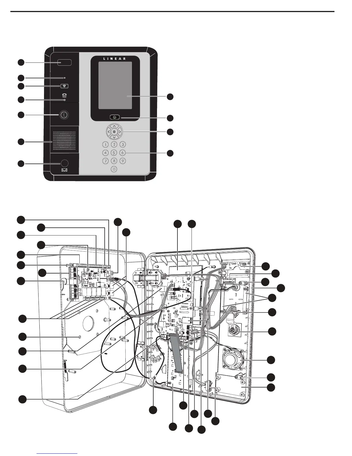
Component Locations
1. Optional Camera
2. Microphone
3. Optional Proximity Sensor
4. TTY Jack
5. Cabinet Lock
6. Speaker
7. Optional Postal Lock
8. Touch Screen Display
(EN-2M7 only)
9. Home Button
10. Navigation Keys
11. Lighted Panel
12. CPU Board
13. USB Port
14. Light Sensor Board
15. Tamper Switch
16. 3-Point Locking Latch
17. Microphone
18. Brackets for Optional Prox
Reader
19. TTY Jack
20. Cabinet Lock
21. Speaker
22. 3 Point Locking Latch
23. Postal Lock Cover
24. Lan Port
25. Not Used
26. Postal Lock Switch
27. Tamper Input
28. Postal Lock Input
29. 12 VDC Input
30. Keypad Board
31. Earth Ground Stud
32. Camera Power
33. SD Memory Card Slot
34. Remote Port
35. Pedestal Mounting Holes
36. Relay Outputs
37. 3-Point Locking Latch
38. Door Position (DSM) Exit
Request (Rex) & Auxiliary
Inputs
39. Input/Output Board
40. Reader “A” (Weigand)
41. Reader “B” Type Jumper
42. Reader “B” (Weigand)
43. Not Used
44. 12 VDC Input
45. Power Fault Input
46. Peripheral Ports (2)
EN-2M7 Displayed
 Loading...