4
GND
GND
REX
GND
GND
REX
GND
AI5
GND
AI6
GND
DOOR "A"
LOCK
RELAY
COM
NC
NO
COM
NC
NO
COM
NC
NO
COM
NC
NO
12V
LED
BUZ
D0 IN
D1 IN
D1 OUT
D0 OUT
12V
LED
BUZ
D0 IN
D1 IN
GND
D1 OUT
D0 OUT
DVAL
PCLK
DSM
DSM
DOOR "A"
AUXILIARY
RELAY
DOOR "B"
LOCK
RELAY
DOOR "B"
AUXILIARY
RELAY
ACCESS DENIED
ACCESS GRANTED
INVALID CARD
READER "A" POWER
READER "A" INDICATORS
ACCESS DENIED
ACCESS GRANTED
INVALID CARD
READER "B" POWER
READER "B" INDICATORS
DOOR "A" DSM
DOOR "A" REX
DOOR "A" AUXILIARY
DOOR "B" DSM
DOOR "B" REX
DOOR "B" AUXILIARY
RS-422 TX STATUS
RS-422 RX STATUS
DOOR "A" LOCK RELAY ACTIVE
DOOR "A" AUXILIARY RELAY ACTIVE
DOOR "B" LOCK RELAY ACTIVE
DOOR "B" AUXILIARY RELAY ACTIVE
COMMUNICATIONS ERROR
RELAY MANUAL
MODEM POWER
USB ENABLED
RS-422 ENABLED
HEARTBEAT
POWER GOOD
POWER ON
PERIPHERAL "A" TRAFFIC
PERIPHERAL "B" TRAFFIC
RESET
BOOT
I/O BOARD & MODE M
INDICATORS
RING
POWER
TX
RX
INPUTS
OUTPUT S
MODEM
• READER POWER lights showing power is being supplied to Reader #1 or
Reader #2.
•
INVALID CARD lights when a credential’s data read is not a valid data
string.
•
ACCESS GRANTED lights when a credential has been successfully
decoded and the Cardholder has been granted access.
•
ACCESS DENIED lights when a credential has been successfully decoded
and the Cardholder has been denied access.
•
DOOR “A” DSM lights when Door Relay “A” Door Switch Monitor input is
activated.
•
DOOR “A” REX lights when Door “A” Request-to-Exit input is activated.
•
DOOR “A” AUX lights when Door “A” auxiliary input is activated.
•
DOOR “B” DSM lights when Door Relay “B” Door Switch Monitor input is
activated.
•
DOOR “B” REX lights when Door “B” Request-to-Exit input is activated.
•
DOOR “B” AUX lights when Door “B” auxiliary input is activated.
•
DOOR “A” LOCK RELAY lights when Door Lock Relay “A” is energized.
•
DOOR “A” AUX RELAY lights when Door Auxiliary Relay “A” is energized.
•
DOOR “B” LOCK RELAY lights when Door Lock Relay “B” is energized.
•
DOOR “B” AUX RELAY lights when Door Auxiliary Relay “B” is energized.
•
COMMUNICATIONS ERROR lights when there is network error.
•
RELAY MANUAL lights when a relay has been activated manually.
•
MODEM POWER lights when the telephone modem has power.
•
USB ENABLED lights when the USB Port has been enabled.
•
HEARTBEAT lights when the system is live and running.
•
POWER GOOD lights when system power is within specication.
•
POWER ON lights when the system is receiving power.
•
BOOT lights during system reboot.
•
RESET lights during system reboot.
•
PERIPHERAL “A” TRAFFIC lights during Peripheral “A” trafc.
•
PERIPHERAL “B” TRAFFIC lights during Peripheral “B” trafc.
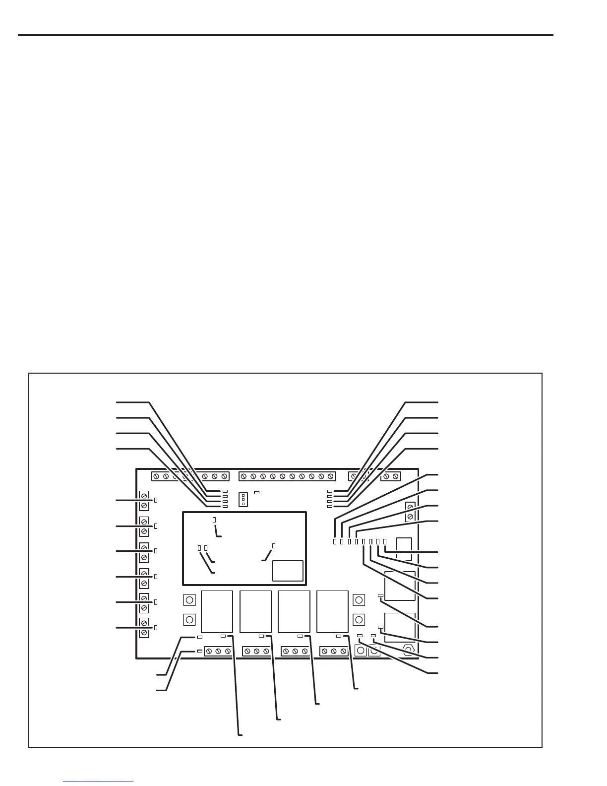
System Diagnostics
LED indicators on the I/O Board and CPU Board are for monitoring the system during operation. When calling for technical assistance, the Technical
Services Department may ask the installer to use these indicators to diagnose the system.
I/O Board & Modem Indicators
33 LED indicators are on the I/O Board. Refer to the gure for the location of each indicator.
 Loading...