26
GND
GND
REX
GND
GND
REX
GND
AI5
GND
AI6
GND
COM
NC
NO
COM
NC
NO
COM
NC
NO
COM
NC
NO
12V
LED
BUZ
D0 IN
D1 IN
D1 OUT
D0 OUT
12V
LED
BUZ
D0 IN
D1 IN
GND
D1 OUT
D0 OUT
PDAT
PCLK
DSM
DSM
FACTORY RESET
I/O BOARD
PUSHBUTTONS
CPU BOARD
PUSHBUTTONS
NETWORK RESET
ADMIN RESET
CPU RESET
DOOR "A"
LOCK RELAY
SYSTEM BOOT
SYSTEM RESET
DOOR "A"
AUX RELAY
DOOR "B"
LOCK RELAY
DOOR "B"
AUX RELAY
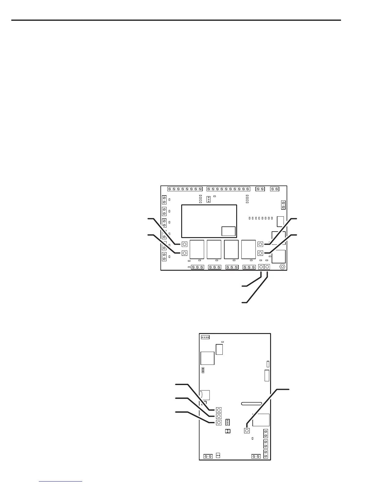
Internal Controls
I/O board Pushbuttons
Six pushbuttons are on the I/O Board. Refer to the gure for the location of each pushbutton. The LOCK / AUX relays can activate Construction
Mode, which allows for manual control of doors and gates to keep them open during heavy construction or other high level trafc.
• DOOR “A” LOCK RELAY button manually activates the Door “A” Lock Relay.
• DOOR “A” AUX RELAY button manually activates the Door “A” Auxiliary Relay.
• DOOR “B” LOCK RELAY button manually activates the Door “B” Lock Relay.
• DOOR “B” AUX RELAY button manually activates the Door “B” Auxiliary Relay.
• SYSTEM BOOT button reboots the entire system.
• SYSTEM RESET button resets the entire system.
CPU board Pushbuttons
Four pushbuttons are on the CPU Board. Refer to the gure for the location of each pushbutton.
• FACTORY RESET button resets the system to the factory defaults. PRESSING FACTORY RESET WILL DELETE ALL PROGRAMMING AND
CARDHOLDER INFORMATION.
• NETWORK RESET button resets
and restarts the system network.
• ADMIN RESET button resets the
unit’s admin code.
• CPU RESET button resets and
restarts the system CPU.
 Loading...