19
Operational Postal Lock
A postal lock can be installed in the EC / EN Series unit to provide keyed access for the postal service. The unit’s case is designed to accept a U.S.
Postal Service postal lock. When the postal lock is engaged, the programmed output relay will activate.
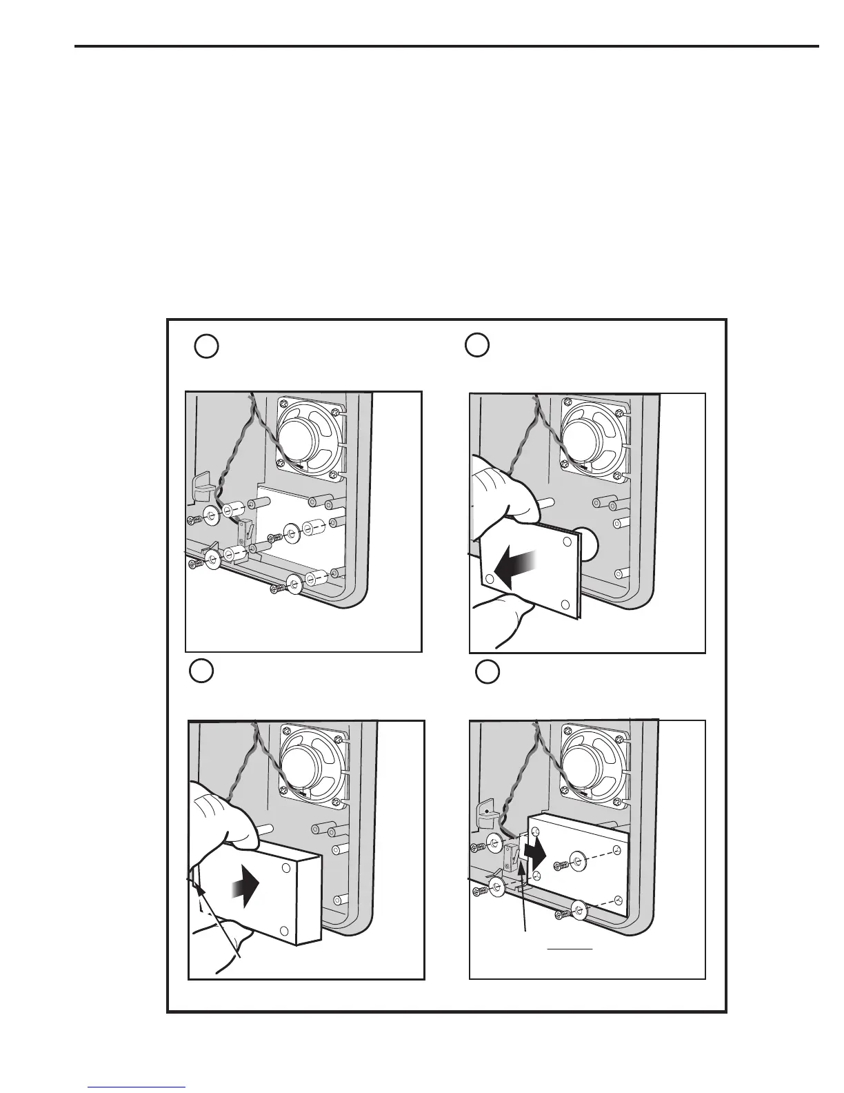
Postal Lock Installation
1. Cut and discard the tie-wrap that is holding the postal lock switch engaged.
2. Remove the four screws that retain the postal lock cover plate.
3. Remove the postal lock cover plate. The postal lock cover plate will not be used and can be discarded.
4. Install the postal lock assembly onto the four studs. The postal lock’s moving plunger should point towards the middle of the faceplate, towards
the postal lock switch (see gure).
5. Secure the postal lock with the four screws.
6. NOTE: Be sure the postal lock’s plunger actuates the microswitch. Adjust the postal lock then test the action until the microswitch fully actuates.
7. Tighten the four screws after the adjustment and testing is complete.
8. When programming the system, set the postal lock option to activate the desired relay output.
REMOVE SCREWS, SPACERS,
AND WASHERS
REMOVE AND DISCARD PLATE
AND SPACERS
INSTALL POSTAL LOCK
1
2
3
4
PLUNGER POINTS TO LEFT
REINSTALL 4 SCREWS AND
WASHERS TO SECURE POSTAL
LOCK IN PLACE
PLUNGER MUST BE
PUSHED IN WHEN INSTALLING
 Loading...