17
12 VDC
POWER INPUT
12V
LED
BUZ
D0 IN
D1 IN
GND
D1 OUT
D0 OUT
DVAL
PCLK
INPUT / OUTPUT
BOARD
IN/OUT READER
SHARED TERMINAL
ENTRY "IN" WEIGAND 1
11-13V
LED
BUZ
D0 IN
D1 IN
GND
D1 OUT
D0 OUT
DVAL
PCLK
EXIT "OUT" WEIGAND 2
11-13V
LED
BUZ
D0 IN
D1 IN
GND
D1 OUT
D0 OUT
DVAL
PCLK
White
White
Wiegand Accessories
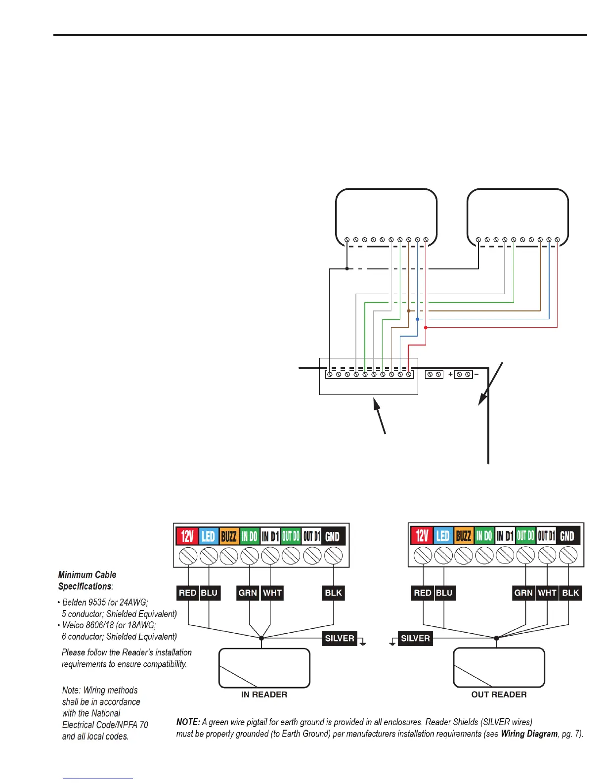
The unit’s four Wiegand inputs (WIEGAND #1 IN/OUT & WIEGAND #2 IN/OUT) can be connect to Wiegand output accessories capable of reading
up to 64 bit formats. The Wiegand format is a common standard for access control equipment. A typical application would be to add swipe card or
proximity readers to the system. Readers can be installed as primary “in readers” (entry) for each door as well as optional secondary “out readers”
(exit).
The maximum power available for an individual reader is 750 mA @ 11-13 VDC with a combined maximum of 1.5A for the unit. Determine the
reader’s power consumption by referring to the documentation included with the reader. Exceeding the maximum current for individual readers or for
the system will damage the protection fuses and void the warranty.
NOTE: Remove Excess Shield. Exposed Shield can cause interference or shorts. Tape off to make sure no shield is exposed.
NOTE: When using Wiegand devices for Reader
“B”, Reader “B” select jumper must be set to Wiegand
position (default).
1. Mount and install the Wiegand accessory as described in
its installation instructions.
2. Route the cable from the unit to the accessory.
Recommended cables:
• Belden 9535 (or 24AWG; 5 conductor; Shielded
Equivalent)
• Weico 8606/18 (or 18AWG; 6 conductor;
Shielded Equivalent)
3. Connect color-coded wires from reader’s wiring harness
to cable.
4. Connect the cable to the appropriate Wiegand READER
terminal on the unit (see Wiegand wiring diagram).
IMPORTANT: Reader shields must be properly
grounded per the manufacturers installation
requirements. See diagram for shield connections.
Manufacturers Wiring Recommendation
 Loading...